EUKYX-199-2100_G5S2_Instruction_Vol2_E.pdf - 第253页
EUKYX 6-16 199-2100 4.2 "Stkr .Area Edit" Window ( 1 1 ) Press the [Appl y] but ton. (Th e "Confirm " wind ow will be displayed). ( 1 2) Press the [OK ] but ton. ( The editing op eration will be e nde…
EUKYX
6-15199-2100
4.2 "Stkr.Area Edit" Window
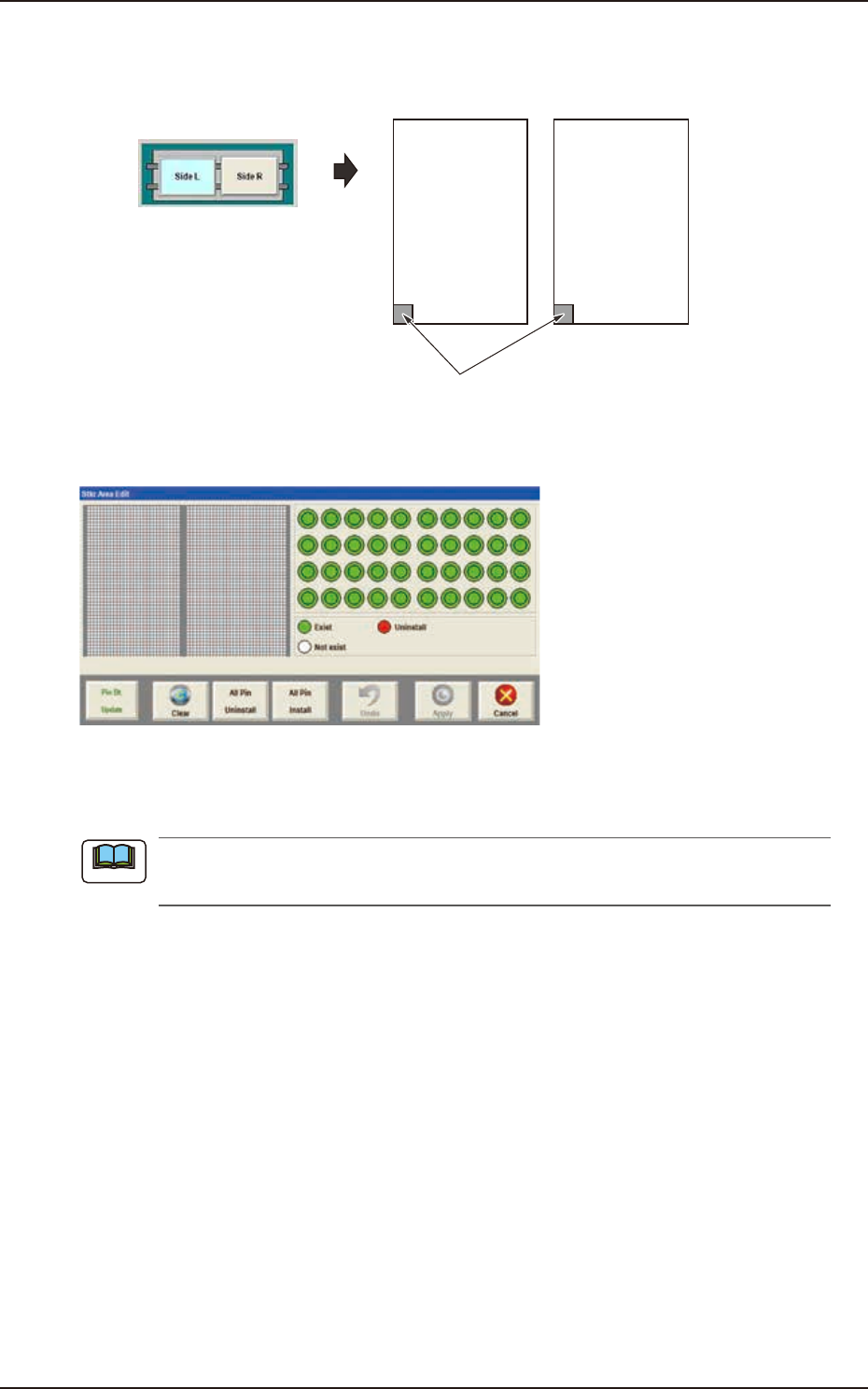
(8) Using the PCB positioning select button, select the stock area for which the parameters are
edited.
Side L Side R
Stkr.Area
PCB positioning select button
F2F17
(9) Press the [Stkr Area Edit] button to display the following window.
F2F1
(10) Edit the parameters in the stock area image display section so that the setup condition is
the same as that for the support pins in the stock area.
When the setup operation is stopped due to an error, press the [Clear] button to clear the
arrangement data for the PCB support pins on the backup base.
Note
EUKYX
6-16199-2100
4.2 "Stkr.Area Edit" Window
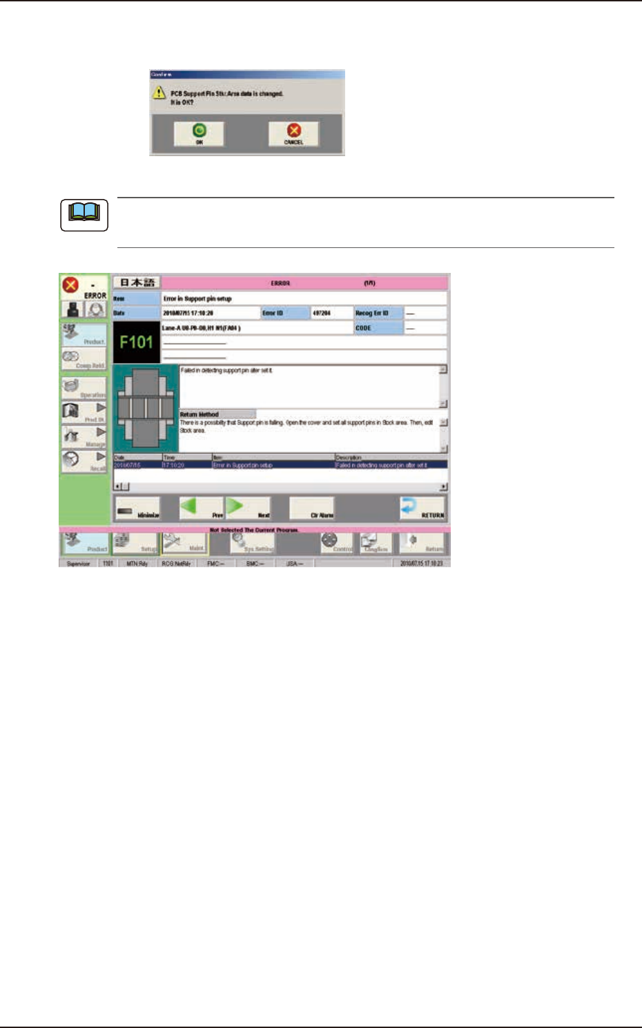
(11) Press the [Apply] button. (The "Confirm" window will be displayed).
(12) Press the [OK] button. (The editing operation will be ended).
F2F19
When any error occurs, the PCB support pins should be re-setup.
Perform the procedure from Step (3).
F2F20
Note
EUKYX
6-17199-2100
5. "NOZ.CHG." Window
5. "NOZ.CHG." Window
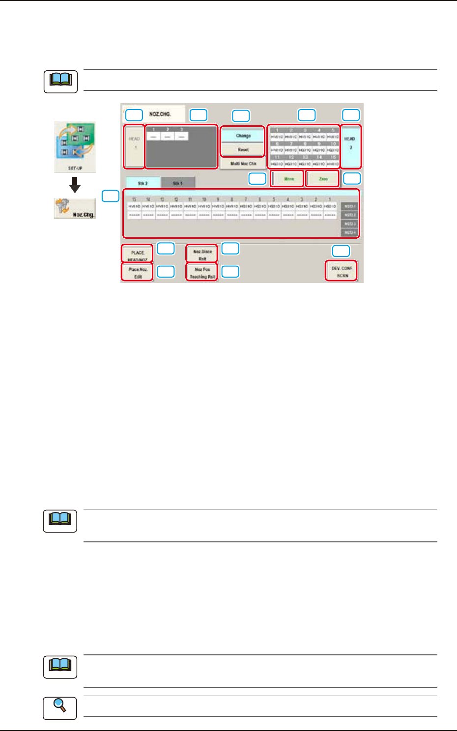
For the nozzle change, the "Overall Setup" or "Manual Setup" operation is performed.
The window shows the condition where a multi-functional head is mounted onto the head No. 1 position.
[1]
[2]
[4]
[5]
[6]
[7]
[8]
[9]
[10]
[11]
[3] [3][2]
Graphic
Development
F2F21
[1] "Nozzle Stocker Status Indicator" Panel
Indicated is the status of the nozzle stockers. The address that nozzle stocker is not set is not
displayed. (Example: “NST2-3 and “NST2-4“ above)
[2] "Vacuum Nozzle Status Indicator" Field
Indicated is the status of the nozzles attached to each head.
[3] Head Selection Buttons
Press the [Head 1] or [Head 2] button to select the head for which some nozzles should be
changed. The background color of the selected button turns light blue.
[4] Nozzle Operation Buttons
The following buttons are provided.
When the [START] button on the operation panel is pressed within 10 seconds after the
button corresponding to the required operation is selected and the [Move] button is pressed,
the machine performs the selected operation for the nozzle.
[Change] Button
When pressed, this button attaches the vacuum nozzle to the placement head.
When the vacuum nozzles (to be used after a program change operation) are prepared in the
extended stocker (option), they are stored and attached in succession.
[Reset] Button
When pressed, this button stores the vacuum nozzle in the object nozzle stocker.
[Multi Noz Chk] Button
When pressed, this button checks if the multi nozzle set on the nozzle stocker is correct or not
.
[5] [Move] Button
Select the work of the nozzle operation buttons. Press the [Move] button. When the [START] button
on the operation panel is pressed within 10 seconds, the selected nozzle operation is performed.
When the nozzle quantity is not enough in this operation, the required nozzles are displayed
on the “Nozzle Check” window.
Refer to “3. “PP CHANGE” Window” for how to use the “Nozzle Check” window.
Note
Note
Note
Reference