EUKYX-199-2100_G5S2_Instruction_Vol2_E.pdf - 第285页
EUKYX 6-48 199-2100 7.3 "COMP RCG" T est Window [P ick -up] Butt on • "Feeder" is sele cte d for "Pick - up mode" When this button is pressed and with in 1 0 se conds, the [ST ART ] button o…
EUKYX
6-47199-2100
7.3 "COMP RCG" Test Window
[6] [Edit] Button
When this button is pressed, the test ID selected in [1] is edited.
Refer to “Chapter 3 Component Library”, for the editing procedure.
[Img Save] Button
When this button is pressed, the "Img Save" window appears.
This window is used to save the test results.
[Noz Chg] Button
When this button is pressed, the "NOZ.CHG." window appears.
Refer to “5. “NOZ.CHG.” Window” for the details of the "NOZ.CHG." window.
[7] [Bk.] Button
When this button is pressed, the "COMP RCG" test window is returned.
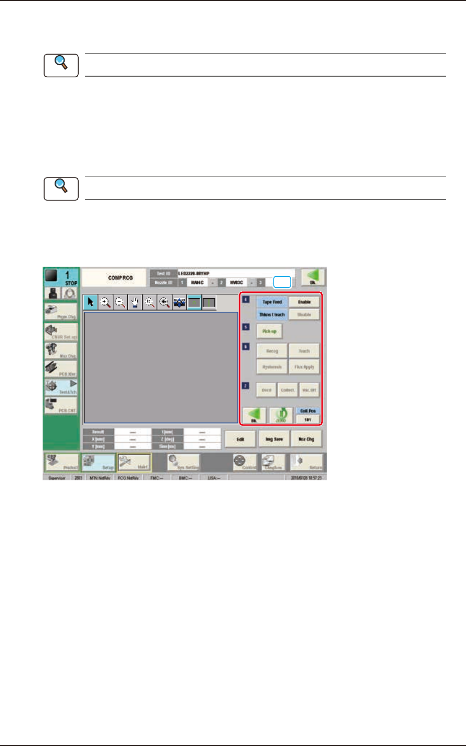
[8] Operation Buttons (Second Page)
[10]
F2F54
■
Tape Feed
[Enable] Button : When this button is pressed, the tape is fed when the test component is
picked up from the feeder.
[Disable] Button
: When this button is pressed, the tape is not fed when the test component
is picked up from the feeder.
■
Thkns t teach
[Enable] Button : When this button is pressed, the component thickness teaching is
performed.
[Disable] Button
: When this button is pressed, the component thickness teaching is not
performed.
Reference
Reference
EUKYX
6-48199-2100
7.3 "COMP RCG" Test Window
[Pick-up] Button
• "Feeder" is selected for "Pick-up mode"
When this button is pressed and within 10 seconds, the [START] button on the operation panel is
pressed, the head in the block selected using the “[4] Head Sel” button, is moved to the position of
the feeder of which No. has been selected using the [4] Feeder No.” button and the component is
picked up automatically.
• "Mnl." is selected for "Pick-up mode"
The component is picked up by pressing [Pick-up] button and set the component manually to the
nozzle center specified in [4] Noz Select of the head in the block specified in [4] Head Sel.
[Vac. On] Button
This button is displayed when “Mnl.“ is selected for “Pick-up mode“. When a component is picked
up, the button name is changed from [Vac. On] to [Vac. Off]. Pressing the [Vac. Off] button
releases the picked up component.
[Recog] Button
When this button is pressed within 10 seconds, the [START] button on the operation panel is
pressed, the head in the block selected using the "[4]
Head Sel" button, is moved to the component recognition camera position and the component
recognition is executed.
[Teach] Button
This button is selected when new component library registration is performed.
Refer to “7.3.6 Windows displayed with [Teach] button” for the details.
[Hysteresis] Button
The component deviation in the pick-up operation can be tested using this "Hysteresis test" button,
When this button is pressed, the "Hysteresis Test" window appears.
[Flux Apply] Button
This button is displayed when the optional flux apply unit is set. Pressing this button displays the
“Flux Apply“ window. The thickness of the applied flux can be measured.
[Cop. Test] Button
This button is displayed when the optional coplanarity check function is set. Pressing this button
displays the “Cop.Test“ window. The uniformity of the bottom most surface of component can be
measured.
[Dscd] Button
When this button is pressed, the component is disposed of according to the component library data.
When this button is pressed, all the axes of the selected XY beam are zeroed.
[Collect.] Button
This button is used when collecting component manually.
When this button is pressed and within 10 seconds, the [START] button on the operation panel is
pressed, the head is move to the lane No. specified using the “Coll. Pos” button.
[Vac. Off] Button
This button changes the ON/OFF of nozzle vacuum. The button name is changed to [Vac. ON] or
[Vac. OFF] depending on the vacuum status.
After moving the head to the specified position and put your hand under the component, press the
button to release the component and collect it with hand.
[Bk.] Button
When this button is pressed, the previous page appears.
[ZERO] Button
Coll.Pos
Using this button, the test component collection position is specified.
Reference
EUKYX
6-49199-2100
7.3 "COMP RCG" Test Window
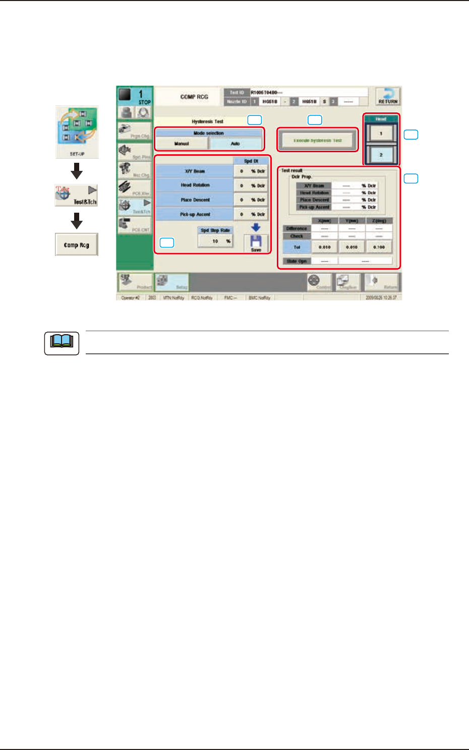
7.3.4.1 Hysteresis Test
Pressing the [Execute hysteresis Test] button displays the window below. This test supports the data
settings for the beam speed reduction in the component pick-up specified in the component library,
review of the rotation speed reduction and beam and rotation speed reduction setup.
Graphic
Development
[1]
[2]
[3]
[5]
[4]
F2F55
When the tab sheet is changed to the other one, the recognition window can be confirmed.
[1] Mode Selection
Using the following buttons, the test mode is setup.
[Manual] Button
The hysteresis test is performed based on the data set in the "Hysteresis Manual Setup"
window.
[Auto] Button
When this button is selected, the hysteresis test operation procedure is repeated with the
speed increase in increments of 1% of the speed reduction value based on the data set in
the "Hysteresis Auto Setup" window.
[2] Spd Dt
The speed reduction setup values for the beam (XY), head rotation, moving up for pick-up, and
moving down for pick-up, are displayed in this pane.
Spd Step Rate
When the "Auto" mode is selected, the current speed reduction rate is displayed in this data
box.
[Save] button
When this button is pressed, the speed reduction value set in “Spd Dt” is saved.
Note