EUKYX-199-2100_G5S2_Instruction_Vol2_E.pdf - 第287页
EUKYX 6-50 199-2100 7.3 "COMP RCG" T est Window [ 3] [Execute hysteresis T est] Butt on When this button is pressed and with in 1 0 se conds, the [ST ART ] button on the o perati on panel i s pressed, the hyste…
EUKYX
6-49199-2100
7.3 "COMP RCG" Test Window
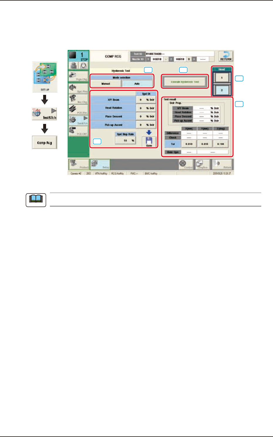
7.3.4.1 Hysteresis Test
Pressing the [Execute hysteresis Test] button displays the window below. This test supports the data
settings for the beam speed reduction in the component pick-up specified in the component library,
review of the rotation speed reduction and beam and rotation speed reduction setup.
Graphic
Development
[1]
[2]
[3]
[5]
[4]
F2F55
When the tab sheet is changed to the other one, the recognition window can be confirmed.
[1] Mode Selection
Using the following buttons, the test mode is setup.
[Manual] Button
The hysteresis test is performed based on the data set in the "Hysteresis Manual Setup"
window.
[Auto] Button
When this button is selected, the hysteresis test operation procedure is repeated with the
speed increase in increments of 1% of the speed reduction value based on the data set in
the "Hysteresis Auto Setup" window.
[2] Spd Dt
The speed reduction setup values for the beam (XY), head rotation, moving up for pick-up, and
moving down for pick-up, are displayed in this pane.
Spd Step Rate
When the "Auto" mode is selected, the current speed reduction rate is displayed in this data
box.
[Save] button
When this button is pressed, the speed reduction value set in “Spd Dt” is saved.
Note

EUKYX
6-50199-2100
7.3 "COMP RCG" Test Window
[3] [Execute hysteresis Test] Button
When this button is pressed and within 10 seconds, the [START] button on the operation panel is
pressed, the hysteresis test is executed.
[4] Head
The buttons showing each head are displayed using images. Selecting one of these buttons, the
head to be used for the hysteresis test is selected.
[5] "Test result" Group Box
In this pane, the test result is displayed.
"Dclr Prop." Group Box
The recommended values for each speed reduction setup are displayed in these data boxes.
Difference X, Y, Z
Each deviation value is displayed in these data boxes.
Check X,Y,Z
Each determination result is displayed in these data boxes.
Tol X,Y,Z
The allowances for the deviation in X/Y direction and Angle Z direction set in the "Hysteresis
Manual Setup" window, are displayed in these text boxes.
EUKYX
6-51199-2100
7.3 "COMP RCG" Test Window
7.3.5 Component Recognition Test Execution Procedure.
There are two ways to execute the component recognition test. One is to attach the component
onto the nozzle manually and the other is to pick-up the component automatically from each
feeder. The each of these procedures is described as follows.
• When attaching the component onto nozzle manually to perform the component recognition test:
(1) Select the test ID in the "COMP RCG" test window.
(2) Press the [Fr.] button. (The component recognition test window will be displayed).
(3) Press the "Mnl." button for the "Pick-up mode".
When the test ID is selected on the "Sel. From Comp Dt" tab sheet, "Feeder" is selected for the
"Pick- up mo de".
(4) Select the head to be used for the component recognition using the button in the "Head
Sel" section.
(5) Press the [Fdr No.] button and enter the lane No., where the component can be attached to
the nozzle manually.
(6) Press the [Noz select] button to select the nozzle No. to be used for the recognition.
(7) Press the [Fr.] button. (The head will be moved and the operation buttons will be changed).
(8) Press the [Pick-up] button and attach the component to the nozzle at its center position.
(9) Press the [Recog] button and within 10 seconds, press the [START] button on the operation
panel.
(10) Confirm the recognition results in the "Results" pane.
• When the recognition result is normal, go to the step (12).
• When the recognition result is abnormal, go to the step (11).
(11) Confirm the component condition in the "Recognition Image Display" section.
When any error is found in the component, replace it.
When there is no error in the component, confirm the data in the test ID and correct it.
After that, perform the component recognition test again.
(12) Execute the hysteresis test.
Refer to “7.3.4.1 Hysteresis Test” for the Main Machine for the details.
(13) Press the [Dscd] or [Collect.] button and within 10 seconds, press the [START] button on the
operation panel.
Discard : When selected, the discard operation is performed based on the component
discharge position data in the test ID.
Collection : When selected, the head is moved to the lane No. specified using the “Coll.
Pos” button and the test component is collected manually.
(14) Press the [ZERO] button and within 10 seconds, press the [START] button on the operation
panel. (The XT beam will be returned to the home position and the test will be ended.)
Procedure
Note
Reference