EUKYX-199-2100_G5S2_Instruction_Vol2_E.pdf - 第293页
EUKYX 6-56 199-2100 [8] [9] [10] [11] [12] [13] [14] [15] [16] [17] F2F59 [ 8] [ ] Butt on Thi s checks the created l ibrary data. [ 9 ] [ ] But ton When this button is pressed, the previ ous l ibra ry data item is bac k…
EUKYX
6-55199-2100
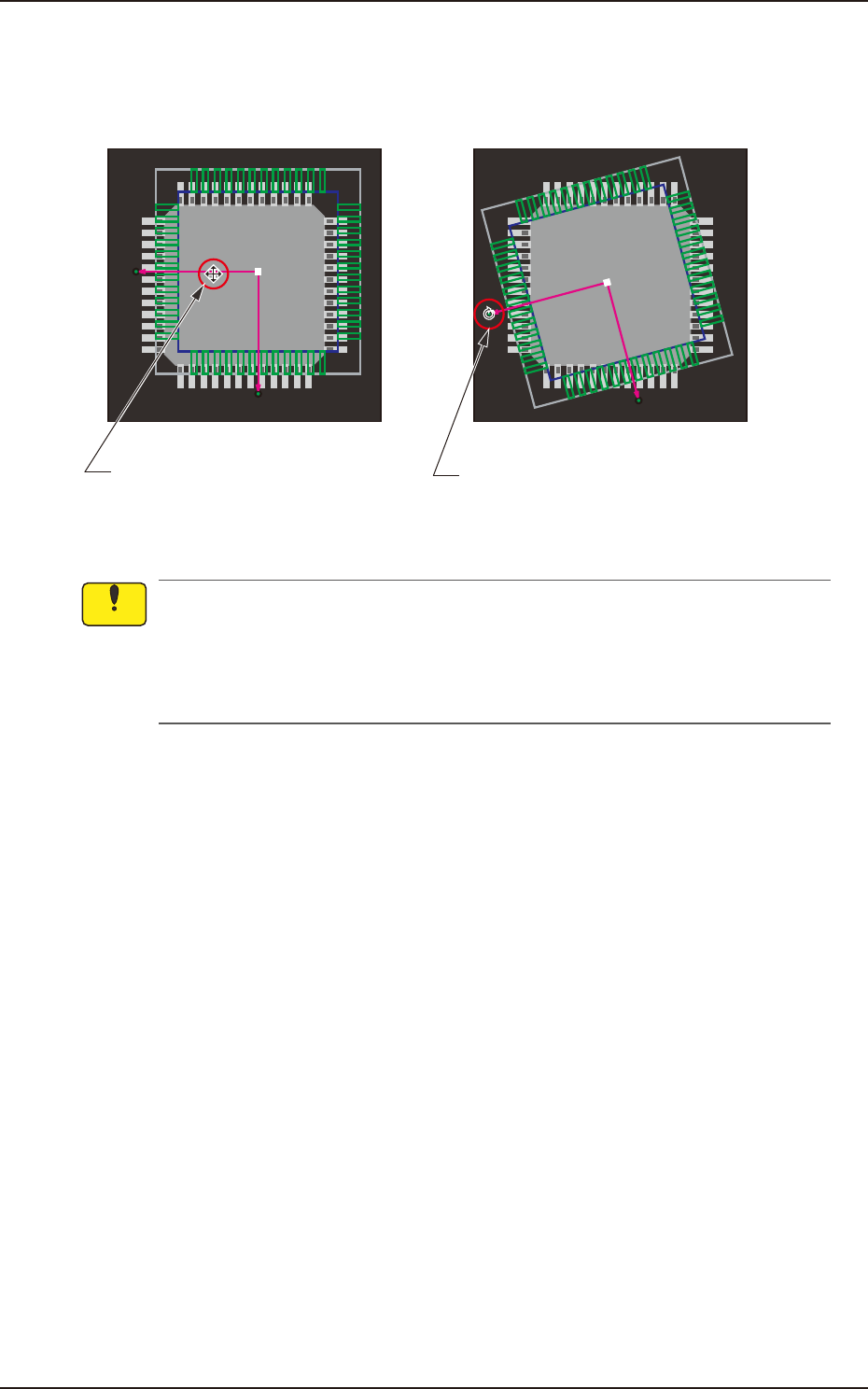
[7] This shows the coordinate system of the component library.
When you click the coordinate graphic and drag the arm portion of the coordinates, the whole
graphic moves. Dragging the end of the arrow mark of the coordinates makes the whole graphic
rotate.
Dragging the line segment of the
arrow extended from the coordinate
point moves the whole graphic.
Dragging the arrowhead rotates
the whole graphic.
F2F58
(a) The coordinate system of the component library is described as "Upper +" and "Right +"
in the instruction manuals, etc. However, as the image of a component is captured from
under the component, it should be noted that the direction of the X axis is reversed (Left +).
(b) Note that dragging a lead, an electrode, etc., other than a graphic coordinate segment
changes the component library data.
Notice
7.3 "COMP RCG" Test Window
EUKYX
6-56199-2100
[8]
[9]
[10]
[11]
[12]
[13]
[14]
[15]
[16]
[17]
F2F59
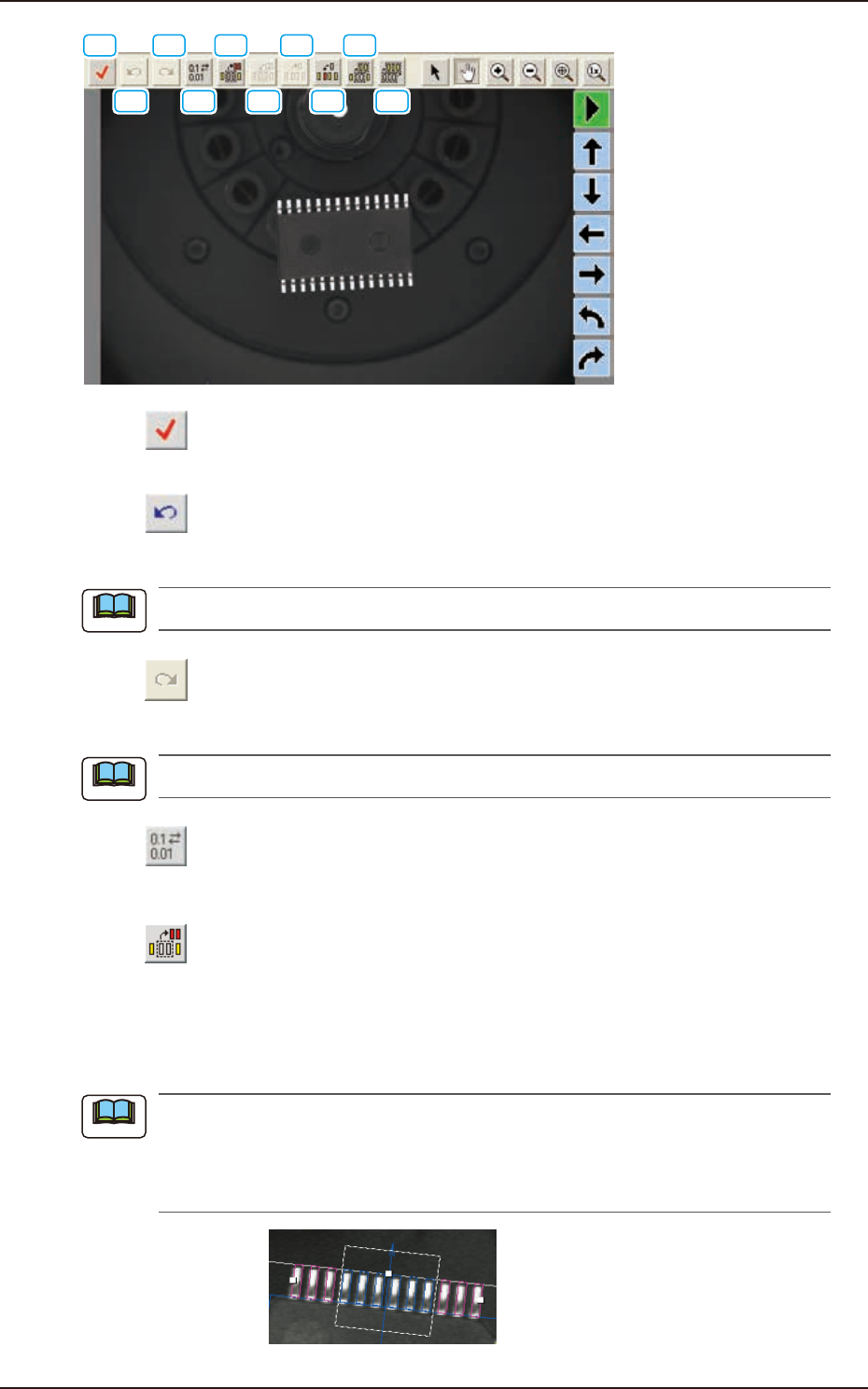
[8] [ ] Button
This checks the created library data.
[9] [
] Button
When this button is pressed, the previous library data item is back.
The component graphic image position is not returned.
[10] [
] Button
When this button is pressed, the previous library data item is returned.
The component graphic image position is not returned.
[11] [
] Button
This opens a data round-up dialog, making it possible to round up the data based on the specified
unit of measurement.
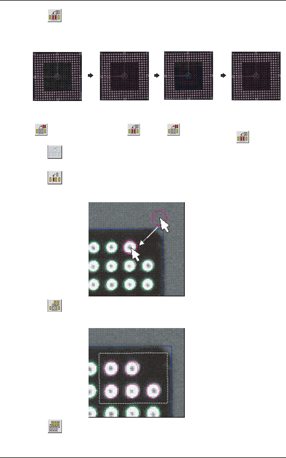
[12] [
] Button
This specifies the missing leads and balls. When you click the lead group or the ball group to be
selected as an object group for missing lead or ball detection, the color of the graphic squares changes
from “Green” to “Yellow”, indicating that this button has become valid. After clicking the button,
enclose the leaded portion to be specified as a missing area with the track ball as shown below.
When “IC (Simple)”, “Connector (Simple)”, or “Other Leaded (Simple)” is selected in the
“Component Shape” text box, one place can be specified for one group. In the case of “IC
(Complex)”, “Connector (Complex)”, or “Other Leaded (Complex)”, up to three places can be
specified. In the case of “BGA/CSP”, up to forty places can be specified.
F2F60
Note
Note
Note
7.3 "COMP RCG" Test Window
EUKYX
6-57199-2100
[13] [ ] Button
This makes it possible to insert leads and balls into the lead and ball missing areas.
The condition that validates the button is the same as [12].
For example, this button can be used effectively for such a BGA as shown below.
Specify the missing
area with the
[ ] button.
Insert balls into
the missing area
with the [ ]
button.
Specify the missing
area again with the
[ ] button.
Insert balls again
into the missing
area with the
[ ] button.
F2F61
[14] [ ] Button
When selected, this button deletes one electrode.
After pressing this button, click the electrode to be deleted.
[15] [
] Button
When selected, this button inserts one electrode. After pressing this button, click any area inside
the window and drag the pointer to the place where the electrode should be inserted.
F2F62
[16] [ ] Button
When selected, this button enables you to enclose several electrodes with a dotted frame for the
selection. This type of selection is useful when several electrodes should be slightly moved at a time.
F2F63
[17] [ ] Button
When selected, this button selects all electrodes.
This type of selection is useful when all electrodes should be slightly moved from the mold center.
7.3 "COMP RCG" Test Window