EUKYX-199-2100_G5S2_Instruction_Vol2_E.pdf - 第322页
EUKYX 6-85 199-2100 7.4 "PEC RCG" T est Window • Move (1 ) Press th e [C rnt.PP .Set Data] but to n on PEC RC G window to display t he “Set Da ta (Crnt.PP . )“ window . Che ck the “Mark Pos X, Y (Move position)…
EUKYX
6-84199-2100
7.4 "PEC RCG" Test Window
7.4.2 PEC Recognition Test Procedure
• PEC Recognition Test Preparation
(1) Open the "PP CHANGE" window from the "Setup" main menu to set the pattern program.
(2) Transfer the PCB to be tested onto the PCB positioning section on the "PCB XFER" window
selected from [Setup] menu or "PCB XFER" window displayed by pressing the [PCB XFER]
button on the "PEC RCG" test window.
(3) Press the [Mark Pos Edit] on the “PEC RCG” window to display the “Mark Pos. Edit“
window. Set the PEC recognition mark on the window.
Press the [Mark Data Edit] button on the “PEC RCG” window to display the “Mark Data
Edit“ window. Set each parameter for the PEC recognition mark.
Selecting [Zone n] and [#n] for the global recognition position in the [Set Data (Crnt.PP.)]
window, can set the position data and PEC recognition mark code.
(4) Move the XY beam so that the PEC recognition mark with which the PEC recognition test is
performed, is within the recognition range (camera view).
For the XY beam movement operation, there are two ways; one is "Move", that is a method to
move to the position set on “[Set Data (Crnt. PP.)] window“. The other one is "Manual Alignment
Operation" where the recognition window is displayed and the XY beam position is adjusted
using the manual alignment operation, viewing the recognition image.
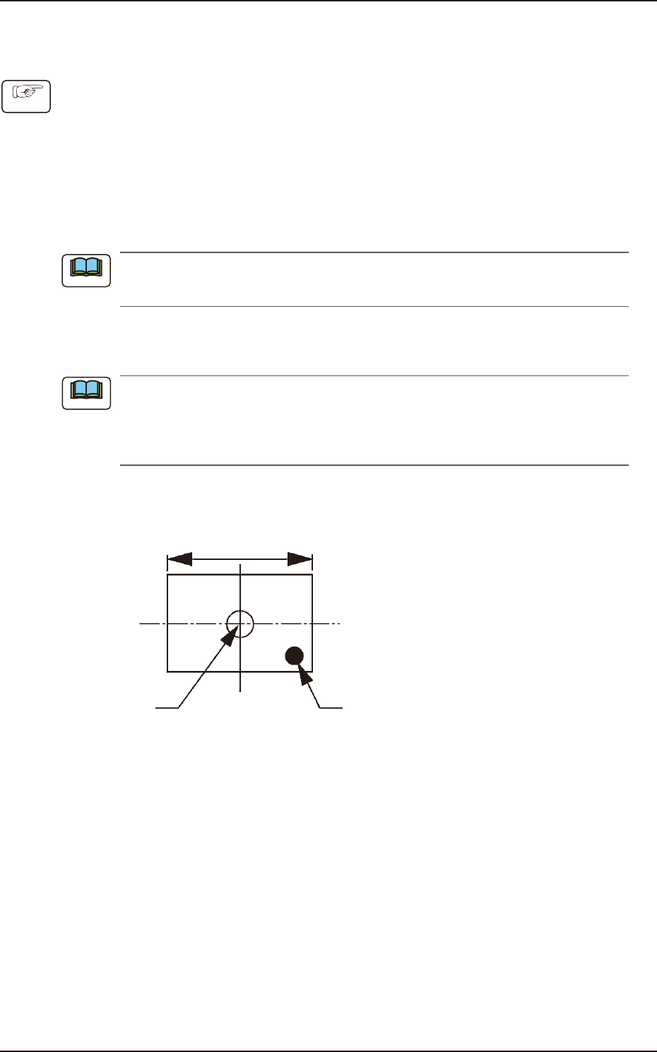
Locate the recognition mark close to a corner of the recognition range as shown in the following
figure.
Center of the
Recognized Image
Recognition Mark
Recognition Range
F2F118
Procedure
Note
Note
EUKYX
6-85199-2100
7.4 "PEC RCG" Test Window
• Move
(1) Press the [Crnt.PP.Set Data] button on PEC RCG window to display the “Set Data (Crnt.PP.)“
window. Check the “Mark Pos X, Y (Move position)“. Pressing the [OK] button returns to the “PEC
RCG“ window.
(2) When the [START] button on the operation panel is pressed within 10 seconds after the
[Move] button is pressed, the XY beam is moved to the specified position.
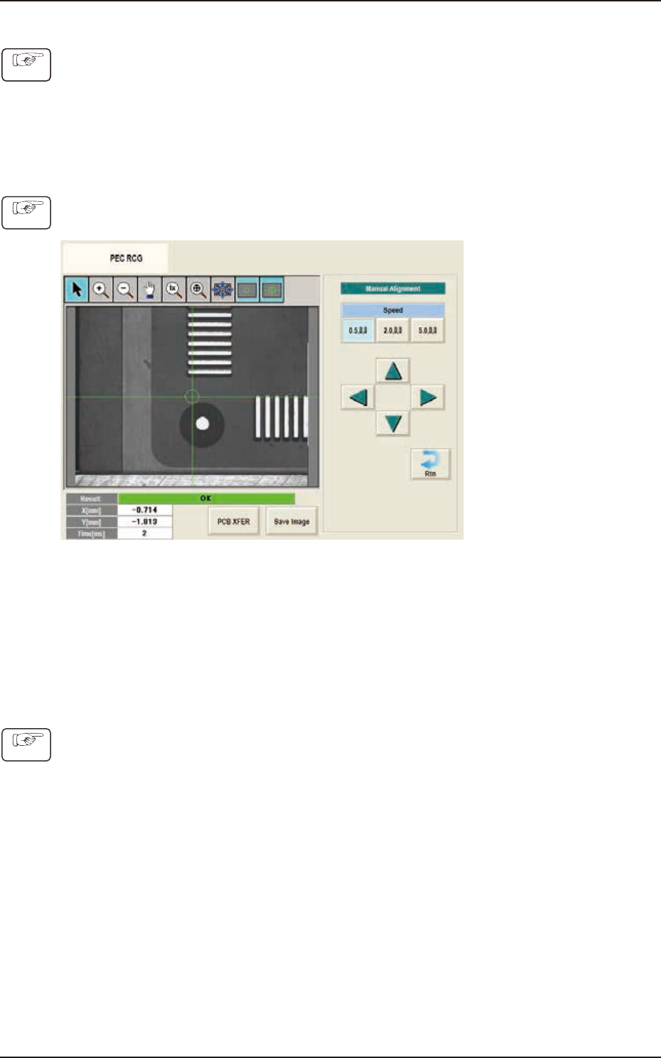
• Manual Alignment
(1) Press the [Manual Alignment] button on the “PEC RCG“ window to display the "Manual
Alignment" window.
F2F119
(2) Setup the XY beam movement speed using with the "Speed" buttons.
(3) Press the direction button (Upper, Right, Lower or Left Arrows) to setup the beam movement
direction.
(4) Press the [START] button on the operation panel within 10 seconds after pressing the
direction button (The XY beam will be moved to the recognition test position.)
• PEC Recognition Test Execution
(1) Press the [START] button on the operation panel within 10 seconds after pressing the [Recog]
button. (The PEC recognition operation are performed.)
• When the recognition test fails, an error (recognition error) window appears.
Collect each parameter referring to the descriptions in the “Error” window and perform
the PEC recognition test again.
• When the recognition test is completed successfully, make a note of collected parameters
and reflect them onto the pattern program data for the product PCB to be tested.
Procedure
Procedure
Procedure
EUKYX
6-86199-2100
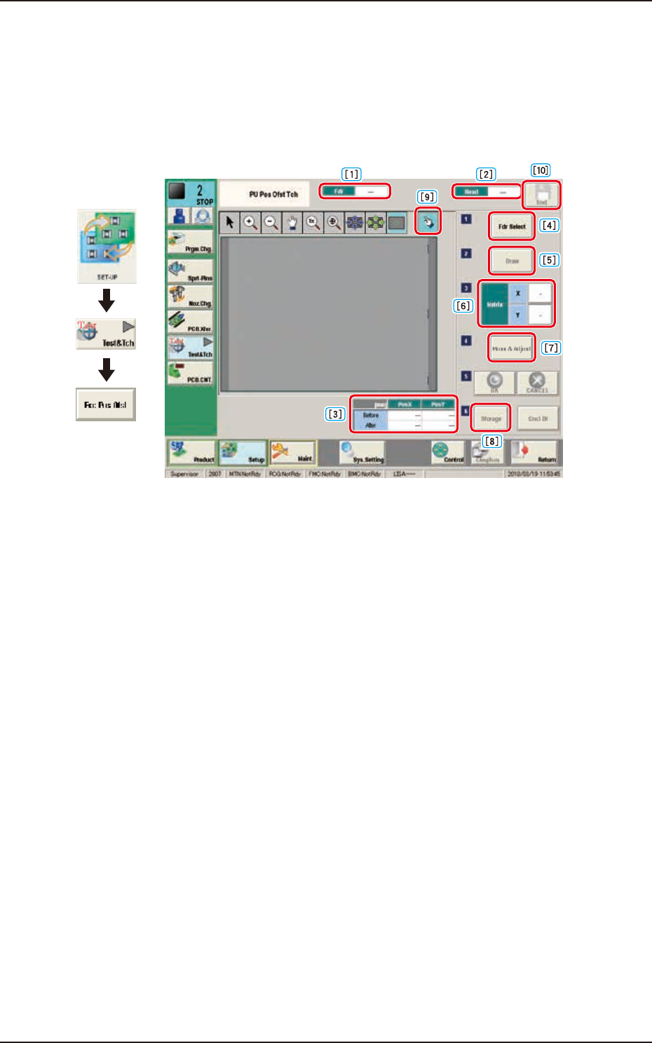
7.5 "PU Pos Ofst Tch" Window
7.5 "PU Pos Ofst Tch" Window
For the components which can not be picked up at its center, the teaching for the pick-up position
is performed.
The manual alignment operation is performed from the current eccentric pick-up position, of which
data obtained by means of adding the data of component center position correction, simple package
shape and pick-up angle.
Graphic
Development
F2F120
[1] Fdr
The Feeder No. to pick-up the component is displayed in this data box.
[2] Head
The head No. to be used to perform the teaching operation is displayed in this data box.
[3] Pick-up Position Offset
The pick-up position correction values on the component library data are displayed for the
components in the specified feeder No.
Before : Value before the teaching operation
After : Resultant value after the teaching operation
[4] [Fdr Select] Button
When this button is pressed, the "Fdr Select Form" window is displayed. In this window, select the
feeder to be used to perform the teaching operation.
[5] [Draw] Button
This button is used for the multi-layer tray feeder (option).
[6] Matrix
This group box is used for the multi-layer tray feeder (option).
[7] [Move & Adjust] Button
Pressing this button displays the move & adjust recognition window and performs manual alignment
operation for the pick-up position.
[8] [Storage] Button
This button is used for the multi-layer tray feeder (option).