EUKYX-199-2100_G5S2_Instruction_Vol2_E.pdf - 第52页
EUKYX 1-2 199-2100 2. "Product" Window 2. " Prod uct" Wi ndo w 2. 1 Loca l Windo w Thi s wi ndow enab les you t o view the cu rrent operati on status and production cond ition s uch as the production …
EUKYX
1-1199-2100
1. Outline of Menus for Automatic Operation
1. Outline of Menus for Automatic Operation
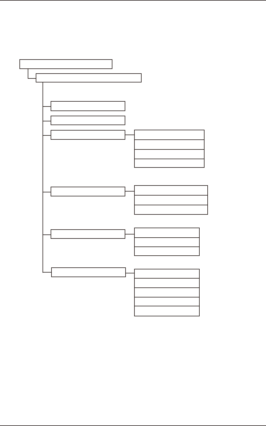
The following shows the hierarchical structure of the menus (including the submenus and windows)
for the automatic operation.
"Product." Window
"Comp.Reload" Window
"OPERATION" Window
"Prod.Dt." Submenu
"Manage" Submenu
"Recall" Submenu
Run Mode Tab Sheet 4.1
Opr.Mode Tab Sheet 4.2
Test Mode Tab Sheet 4.3
Altn Mode Tab Sheet 4.4
PP.Data Chapter 2
Comp Lbry Chapter 3
Temp. Chng. Comp Lbry "2" in "Chapter 3"
Device Err "2" in "Chapter 5"
Comp Rcg Err "3" in "Chapter 5"
Comp Err(Sens) "4" in "Chapter 5"
Mach Info "5" in "Chapter 5"
Disp. Rcg Img dt "6" in "Chapter 5"
Mng.Dt "2" in "Chapter 4"
Cmt.PP.Mng.Dt "3" in "Chapter 4"
Msg Rate Data "4" in "Chapter 4"
Reference Item Nos.
Automatic Operation Main Menu Bar
2
3
F2A1
Menus for Automatic Operation
EUKYX
1-2199-2100
2. "Product" Window
2. "Product" Window
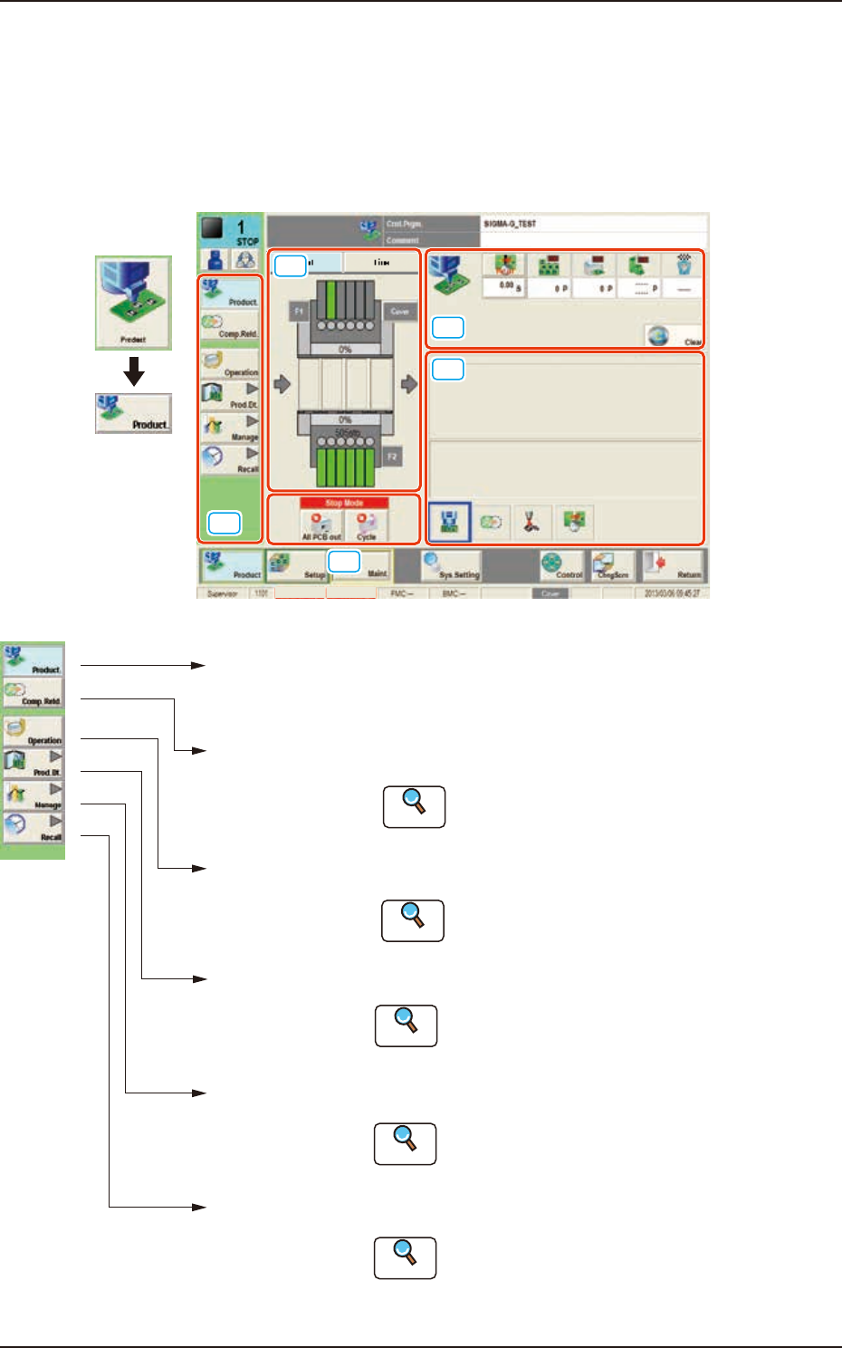
2.1 Local Window
This window enables you to view the current operation status and production condition such as the
production model names (pattern program names), etc., and the information on the prospective number
of finished PCBs and presumable deterioration in the operation rate based on pickup errors, etc.
[1]
[3]
[4]
[5]
[2]
Graphic
Development
MTN:NotRdy RCG:NotRdy
F2A2
[1] “Product.” Main Menu Bar
[Product.]
Main Menu
Opens the "Product" window. In normal cases,
this window opens as an initial one.
[Comp.Reld.]
Main Menu
Opens the "Comp.Reload" window.
Refer to "3. "Comp.Reload" Window"
for details .
[Operation]
Main Menu
Opens the "OPERATION" window.
Refer to "4. "OPERATION" Window"
for details.
[Prod.Dt.]
Main Menu
Opens the "Prod.Dt." window.
:
[Manage]
Main Menu
Opens the "Manage" window.
Refer to "Management Data in chapter 4" for
details.
:
[Recall]
Main Menu
:
:
:
:
Reference
Reference
Reference
Opens the "Recall" window.
Refer to "Recall in chapter 5" for details.
Reference
Refer to "Pattern Program in chapter 2" and
"Component Library in chapter 3" for details.
Reference
F2A3
EUKYX
1-3199-2100
2.1 Local Window
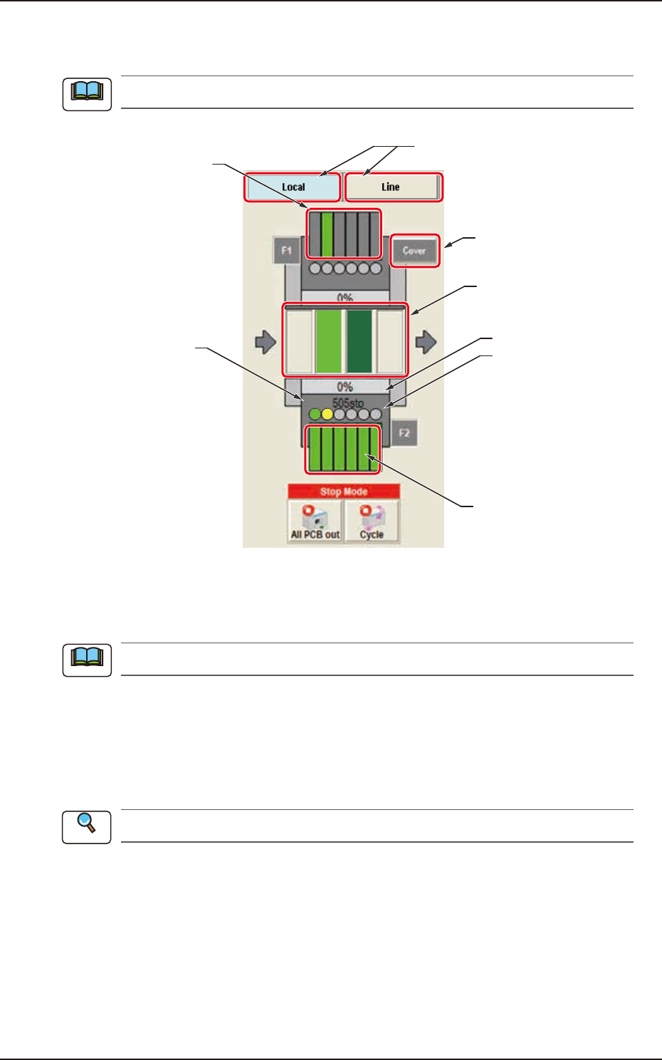
[2] Graphic Display Area
The graphic image of the PCB transfer and component input sections is displayed in this area.
The displayed contents will differ depending on selection of the options.
(2) Feeder status
(Pick-up Rate)
201 to 260
(Feeder
Component Data)
PCB Process
Status
101 to 160
(Feeder Component
Data)
Placement
Step Count
(3)
(4)
(1)
F2A4
(1) Local / Line Change Buttons
Using these buttons, the graphic display section is changed.
When the line consists of a single unit, the line control change button is not displayed.
[Local] Button : When this button is pressed, the graphic image of the single machine is
displayed.
[Line] Button : When this button is pressed, the graphic image of the line is displayed.
The line start or line stop after the completed PCB is discharged from the
line, is performed.
Refer to ”2.2 Line Window” in chapter 1 for the details.
Note
Note
Reference