EUKYX-199-2100_G5S2_Instruction_Vol2_E.pdf - 第76页
EUKYX 1-26 199-2100 4.2 "Opr .Mode" T ab Sheet 4.2 . 1 Re cog Display When the [ Recog Disp lay ] but ton is pressed on the "O pr .Mo de" tab she et, the fol lowi ng window appears. On this w indo w ,…
EUKYX
1-25199-2100
4.2 "Opr.Mode" Tab Sheet
4.2 "Opr.Mode" Tab Sheet
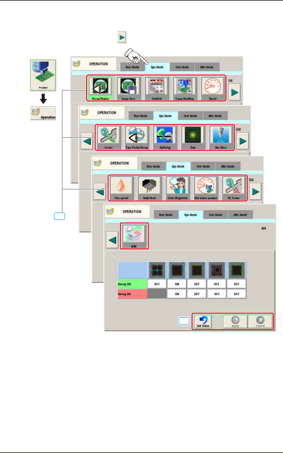
When the [Opr.Mode] tab is pressed, the "Opr.Mode" tab sheet (1st page) appears as an initial one.
Every time the Page switch button [ ] is pressed, 2,3, or 4 page in the “Opr.Mode” is displayed.
[1]
Graphic
Development
"Opr.Mode" Tab sheet (1/4 page)
2/4 page
3/4 page
4/4 page
[2]
F2A23A
[1] “Opr.Mode” Select
The setting is performed in this area for the selected button.
When the setting has been changed, press the [Apply] button to apply the setting.
[2] Common Button
[Init Value] Button
When pressed, the set condition parameters are returned to the initial values.
[Apply] Button
When pressed, the changed setting is applied.
[Cancel] Button
When pressed the changed setting is returned to the one prior to the change.
EUKYX
1-26199-2100
4.2 "Opr.Mode" Tab Sheet
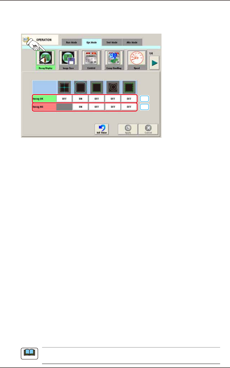
4.2.1 Recog Display
When the [Recog Display] button is pressed on the "Opr.Mode" tab sheet, the following window appears.
On this window, the graphic display setting when the recognition results are displayed, is performed.
[1]
[2]
F2A26A
[1] Recog OK
When the result of recognition is normal, the graphics of the items for which the setting has
been "ON" using the following buttons, are displayed.
[Cross] Button
When selected, this displays a crosshair at the center of the recognized object.
[Circle] Button
When selected, this displays a circle at the center of the recognized object.
[Outside] Button
When selected, this displays the outline of the recognized object.
[Nozzle Outside] Button
When selected, this displays the outline of the vacuum nozzle that was used to recognize a
component.
[Detect Pos] Button
When selected, this displays the detection area, detected corner or edge position.
[2] Recog NG
When the result of recognition is abnormal, the graphics of the items for which the setting
has been “ON” using the following buttons, are displayed.
[Circle] Button
When selected, this displays a circle at the center of the recognized object.
[Outside] Button
When selected, this displays the outline of the recognized object.
[Nozzle Outside] Button
When selected, this displays the outline of the vacuum nozzle that was used to recognize a
component.
[Detect Pos] Button
When selected, this displays the detection area, detected corner or edge position.
When the button corresponding to the set item, is pressed, turning ON/OFF of the button can
be performed. Multiple items can be selected.
Note
EUKYX
1-27199-2100
4.2 "Opr.Mode" Tab Sheet
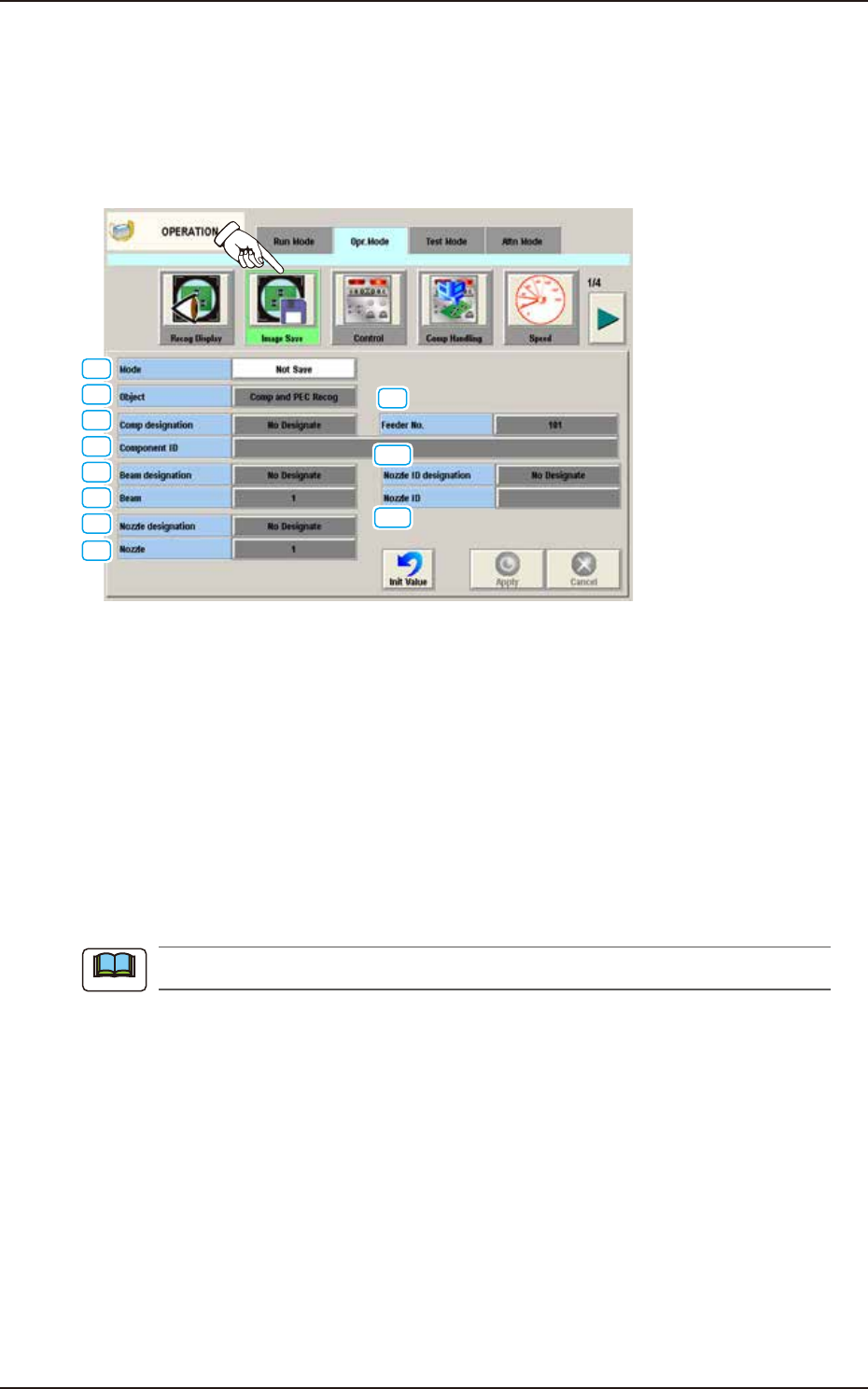
4.2.2 Image Save
When the [Image Save] button is pressed on the "Opr. Mode" tab sheet, the following window
appears. Set parameters in the "Object" and "Select" text boxes to analyze the cause of a recognition
error in comparison with the error image on the monitor.
When "Save" is set in the "Mode" text box, the image which matches the parameters in the "Object"
and "Select" text boxes is stored in memory of the Machine.
[1]
[2]
[3]
[4]
[5]
[6]
[7]
[8]
[9]
[10]
[11]
F2A27A
[1] Mode
Select one of the following options to determine whether or not the recognized image should be
saved.
Not Save : The recognized image is not saved.
Save [Recog NG] : The recognized image is saved only when the recognition results in
"NG" (No Good).
Save [Recog OK] : The recognized image is saved only when the recognition results in
"OK".
Save [Recog NG/OK] : The recognized image is saved when the recognition results in "NG" (Not
Good) or "OK".
When "Not Save" is selected, the other items cannot be set.
Note