EUKYX-199-2100_G5S2_Instruction_Vol2_E.pdf - 第89页
EUKYX 1-39 199-2100 [ 5] Nozzl e Pickup Ascent When this button is pressed, the "No zzle P ic k - Up Ascent" e dit wi ndow op ens. Set the rate of speed r eduction in the da ta entr y field f or the ascendin g …
EUKYX
1-38199-2100
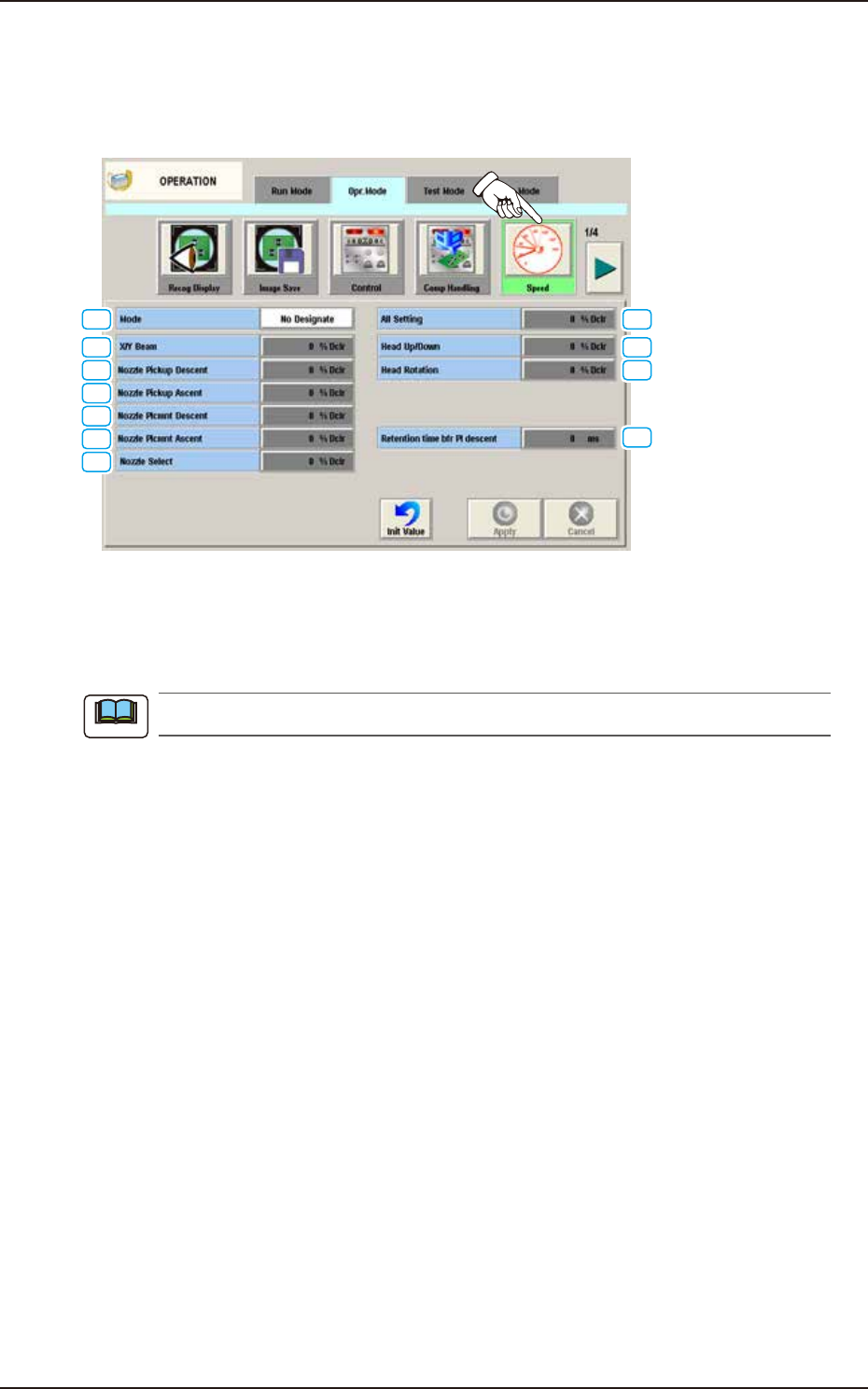
4.2.5 Speed
The following window appears by pressing the [Speed] button on the “Opr. Mode“ tab sheet.
Whether or not the speed upper limit is set, is selected for the operation speed in each unit, which
has been designated in the component library data (speed reduction rate to the maximum speed).
[1]
[3]
[4]
[2]
[9]
[10]
[5]
[6]
[7]
[8]
[11]
F2A31A
[1] Mode
The following buttons can be selected to determine whether or not the running speed reduction
mode should be used.
When "Not Save" is selected, the other items cannot be set.
No Designate
When selected, this button disables you to designate the reduction of the running speed.
Designate
When selected, this button enables you to designate the reduction of the running speed.
In this case, as the following buttons become available, set the rate of each speed reduction.
[2] All Setting
When this button is pressed, the [All Setting] window opens. In this window, set the speed
reduction rate in the data entry field. The set speed reduction rate is reflected on all other settings.
[3] X/Y Beam
When this button is pressed, the “X/Y Beam” entry window is displayed. In this window, set the
speed reduction rate for the X/Y beam in the data entry field.
[4] Nozzle Pickup Descent
When this button is pressed, the “Nozzle Pick-Up Descent” edit window opens.
Set the rate of speed reduction in the data entry field for the descending movement of the nozzle
(nozzle movement to pick up a component from the feeder).
Note
4.2 "Opr.Mode" Tab Sheet
EUKYX
1-39199-2100
[5] Nozzle Pickup Ascent
When this button is pressed, the "Nozzle Pick-Up Ascent" edit window opens.
Set the rate of speed reduction in the data entry field for the ascending movement of the nozzle
(nozzle movement after the nozzle has picked up a component from the feeder).
[6] Nozzle Plcmnt Descent
When this button is pressed, the "Nozzle Plcmnt Descent" edit window opens.
Set the rate of speed reduction in the data entry field for the descending movement of the nozzle
(nozzle movement to place a component on the PCB).
[7] Nozzle Plcmnt Ascent
When this button is pressed, the "Nozzle Plcmnt Ascent" edit window opens.
Set the rate of speed reduction in the data entry field for the ascending movement of the nozzle
(nozzle movement after the nozzle has placed a component on the PCB).
[8] Nozzle Select
When this button is pressed, the "Nozzle Select" edit window opens.
Enter the rate of speed reduction in the data entry field for a series of operations performed when
the nozzle is changed.
[9] Head Up/Down
When this button is pressed, the "Head Up/Down" edit window opens.
Enter the rate of speed reduction in the data entry field for the head upward and downward
movement.
[10] Head Rotation
When this button is pressed, the “Head Rotation” edit window opens.
Enter the rate of speed reduction in the data entry field for the head rotation.
(a) If a higher speed than that specified in this window is set in the component library data,
it is regulated to the specified upper limit.
(b) If a lower speed than that specified in this window is set for some components in the
component library data, it becomes valid.
[11] Retention time bfr Pl descent
The stop time before the moving down for the placement, is set in this data box.
Rang : 0 to 255 ms
Value : 0 ms
Note
4.2 "Opr.Mode" Tab Sheet
EUKYX
1-40199-2100
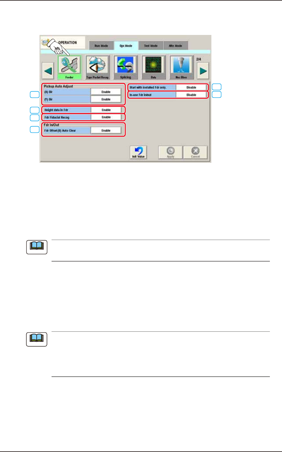
4.2.6 Feeder
The following window appears by pressing the [Feeder] button on the “Opr. Mode“ tab sheet.
[1]
[4]
[2]
[3]
[5]
[6]
F2A32A
[1] Pickup Auto Adjust
This function is used to correct the feeder offset data through statistical processing of the difference
between the nozzle and component center positions calculated during component recognition
according to the parameters specified as "Auto fdr axis adj set" in the "Auto Ope. Set-up" tab sheet
in the "System" window.
The [Enable] or the [Disable] button can be selected for the pickup auto adjust mode.
Each button can be selected separately for the X and Y directions.
The "Auto Ope. Set-up" tab appears when the [Ope. Palam.] button is pressed after pressing
the [Sys. Setting] button on the common menu bar.
►
(X) Dir
Enable:
Select this button to use the automatic feeder axis adjustment function for the X direction.
Disable:
Select this button not to use the automatic feeder axis adjustment function for the X direction.
►
(Y) Dir
Enable:
Select this button to use the automatic feeder axis adjustment function for the Y direction.
Disable:
Select this button not to use the automatic feeder axis adjustment function for the Y direction.
(a) In normal cases, the [Enable] button should be selected.
(b) The designation of the pickup auto adjust function for a specific feeder can be canceled
in the component library data.
(c) When the machine is set in the “RUN” or the “WAIT” mode, the data save operation
(saving of changed settings) cannot be performed.
[2] Height data in Fdr
Enable:
Select this button to use the feeder height data when components are picked up.
Disable:
Select this button not to use the feeder height data when components are picked up.
Note
Note
4.2 "Opr.Mode" Tab Sheet