m220_383_02_process_manual工艺手册.pdf.pdf - 第12页
INTRODUCTION P ROCESS M ANU AL 1.2 Process engineer area description H S OT URFACE 1-2 Figure 1-2 Loadstation The process engineer area is lim ited to th e loadstation onl y. Figure 1-2 shows all relev ant items. The Loa…
INTRODUCTION
P
ROCESS MANUAL
1.Introduction
1.1 General
The horizontal furnaces of Tempress Systems Inc. are developed according to the latest
European directives for Machinery (
98/37/EC), Low Voltage (73/23/EC) and EMC
(
89/336/EEC).
The Tempress Diffusion system is a modular horizontal furnace designed to process (silicon)
wafers as part of the manufacturing technology of semiconductor, optical, MEMS and solar
devices.
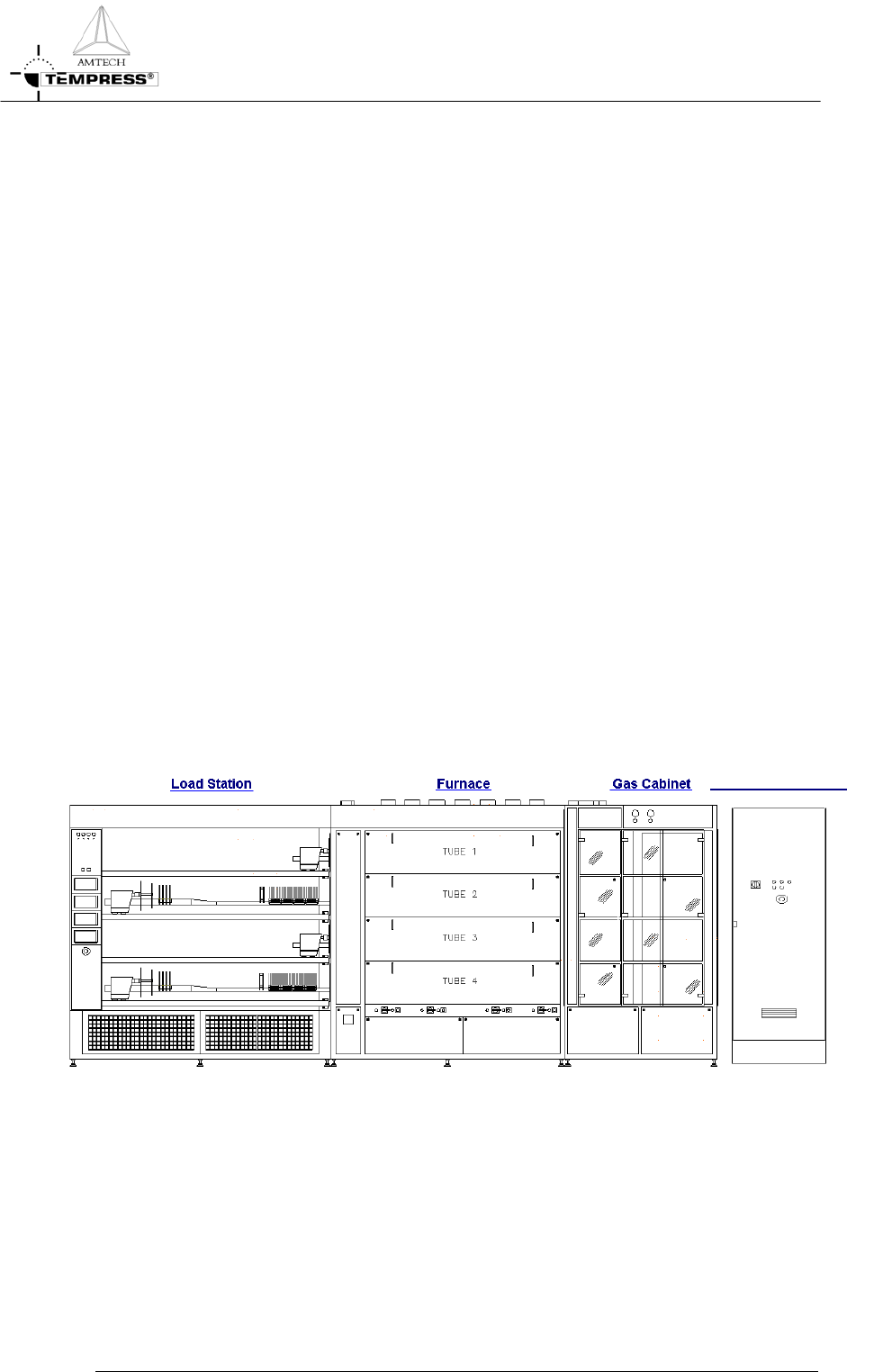
Figure 1-1 shows an example of a L-shape diffusion system with 4 process tubes shown
without the partition of a cleanroom wall.
It is a right-handed system, defined according to the position of the furnace relative to an
operator.
Usually the system contains more than 1 tube. Based on the number and size of tubes, the
system is referred to as a 2, 3 or 4 stack.
Figure 1-1 is an example of a 4-stack system, allowing up to 4 different processes at any time.
The tubes are numbered from 1 to 4, with tube number 1 at the top and tube 4 at the
bottom. All tubes operate fully independently.
Main Power Cabinet
Figure 1-1 Schematic view of a right-handed 4-stack Diffusion System
1-1
INTRODUCTION
P
ROCESS MANUAL
1.2 Process engineer area description
H S OT URFACE
1-2
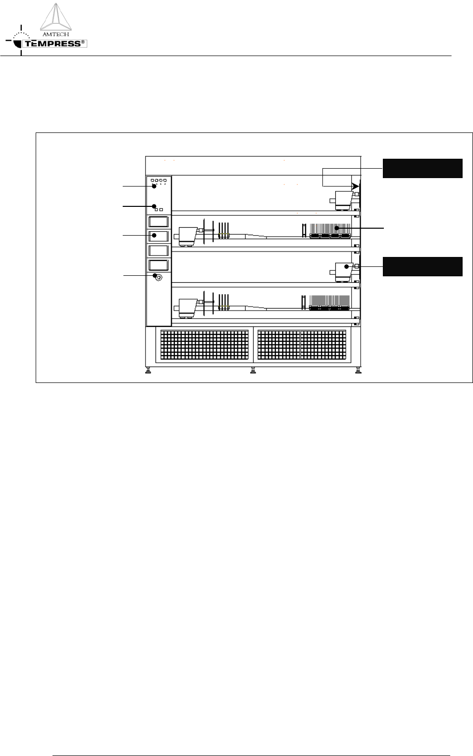
Figure 1-2 Loadstation
The process engineer area is limited to the loadstation only. Figure 1-2 shows all relevant
items.
The Loadstation part of a Tempress System should be placed in the cleanroom. The Furnace
and Gas cabinet can optionally be placed in the greyroom.
To load wafers, several loader types can be implemented, including the (default) inline loader,
the Amtech Atmoscan
®
and the backmounted softlander. To prevent particles on the wafers
during the loading process, a constant horizontal laminar flow is created from the loadstation
into the cleanroom.
The loadstation is powered by 230V and has an illuminated On/Off switch for the fans and
the lights.
The remote control cabinet in the loadstation contains TFT-Touchscreens, one for each
tube. These are the user interface for communication with the Digital System Controllers
(DPC, DTC and DMC).
MOVING PART
W
afers
Buzzer
/
LED
T
ouchscreen
Light/Fan Switch
SAFETY
P
ROCESS MANUAL
2.Safety
This section contains a brief description of the safety features of a Tempress Horizontal
Diffusion System for the process engineer.
Process engineers must have a general knowledge of the technology involved in diffusion
systems. They should understand safety practices outlined in this manual. Process engineers
must have additional knowledge about chemistry and chemicals used in the customer specific
process applications.
The descriptions contained in this user manual are general in nature. The actual furnace may
differ in minor detail from the furnace described in this manual, because of customer specific
requirements or modifications. Please refer to the Tempress Safety manual (M110.00) for a
complete description of available safety features.
2.1 Emergency Off (EMO)
Emergency Off (EMO) buttons are located around the system at accessible locations
according to EN 60204-1 especially EN 418. Pressing an EMO button turns off all power to
the system except to the fans on top of the furnace. This prevents fire hazard as a result of
high heat concentration in the furnace cabinet. Also those parts that are connected to a UPS
facility remain operational.
Press the EMO button when a person is in danger, when there is a fire, a water leak
or any other event that could be hazardous to life.
2.2 Alarm Signals
Alarms and alerts generated by tube controls are presented in several ways:
• Buzzer / LED
• Touch screen
• Light tower
• TSC-II
2.2.1
Buzzer / LED
Visible and audible alarm signals are generated by the process controller (DPC) and the
temperature controller (DTC). The visible signals will be presented with a LED, located
below the buzzer position as shown in
Figure 1-1. Each process is represented by one LED
and buzzer combination.
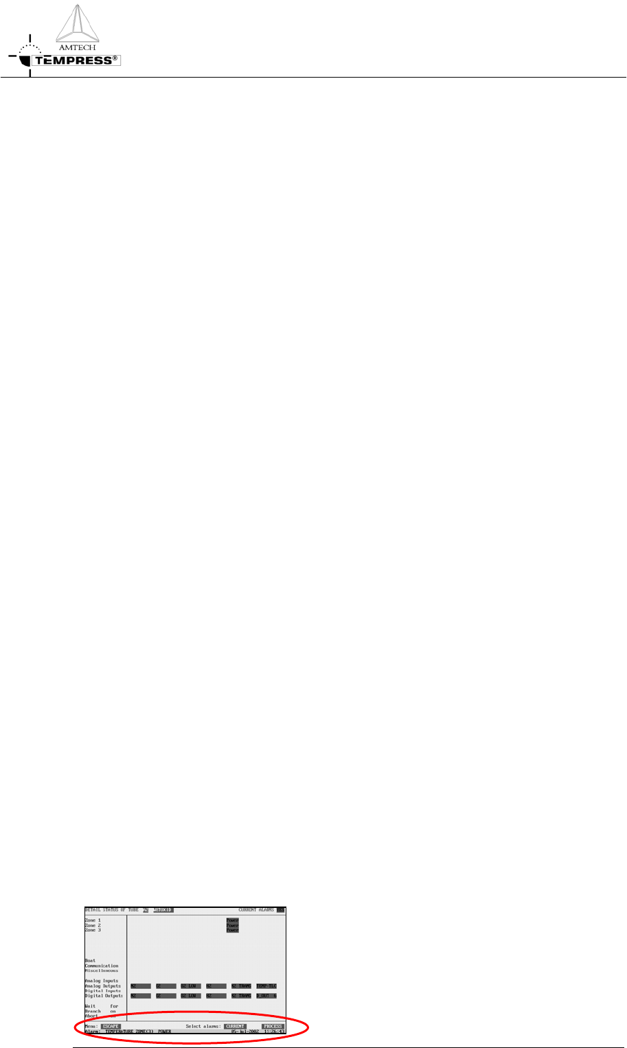
2.2.2
Touchscreen
The visible alarms will be presented on the
touchscreen bottom line. Alarms on the
Touchscreen are always in combination with an
audible signal.
2-2
Touching the screen deactivates the audible signal.