m220_383_02_process_manual工艺手册.pdf.pdf - 第14页
SAFETY P ROCESS M ANU AL 2.2.3 Light tower Alarms generated by the DPC, D TC and DMC will be made visible b y three colors. Eac h color of the light tower represents particul ar circumstances. - Green represents safe, op…
SAFETY
P
ROCESS MANUAL
2.Safety
This section contains a brief description of the safety features of a Tempress Horizontal
Diffusion System for the process engineer.
Process engineers must have a general knowledge of the technology involved in diffusion
systems. They should understand safety practices outlined in this manual. Process engineers
must have additional knowledge about chemistry and chemicals used in the customer specific
process applications.
The descriptions contained in this user manual are general in nature. The actual furnace may
differ in minor detail from the furnace described in this manual, because of customer specific
requirements or modifications. Please refer to the Tempress Safety manual (M110.00) for a
complete description of available safety features.
2.1 Emergency Off (EMO)
Emergency Off (EMO) buttons are located around the system at accessible locations
according to EN 60204-1 especially EN 418. Pressing an EMO button turns off all power to
the system except to the fans on top of the furnace. This prevents fire hazard as a result of
high heat concentration in the furnace cabinet. Also those parts that are connected to a UPS
facility remain operational.
Press the EMO button when a person is in danger, when there is a fire, a water leak
or any other event that could be hazardous to life.
2.2 Alarm Signals
Alarms and alerts generated by tube controls are presented in several ways:
• Buzzer / LED
• Touch screen
• Light tower
• TSC-II
2.2.1
Buzzer / LED
Visible and audible alarm signals are generated by the process controller (DPC) and the
temperature controller (DTC). The visible signals will be presented with a LED, located
below the buzzer position as shown in
Figure 1-1. Each process is represented by one LED
and buzzer combination.
2.2.2
Touchscreen
The visible alarms will be presented on the
touchscreen bottom line. Alarms on the
Touchscreen are always in combination with an
audible signal.
2-2
Touching the screen deactivates the audible signal.
SAFETY
P
ROCESS MANUAL
2.2.3 Light tower
Alarms generated by the DPC, DTC and DMC will be made visible by three colors. Each
color of the light tower represents particular circumstances.
- Green represents safe, operational condition.
- Yellow represents warnings and alerts
- Red represents alarms
See section
2.3 for a full description.
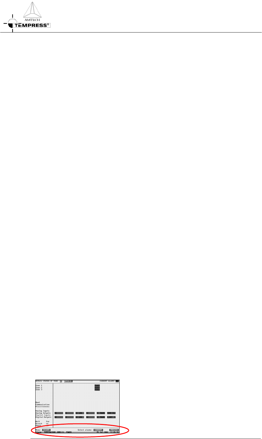
2.2.4
TSC Alarm menu
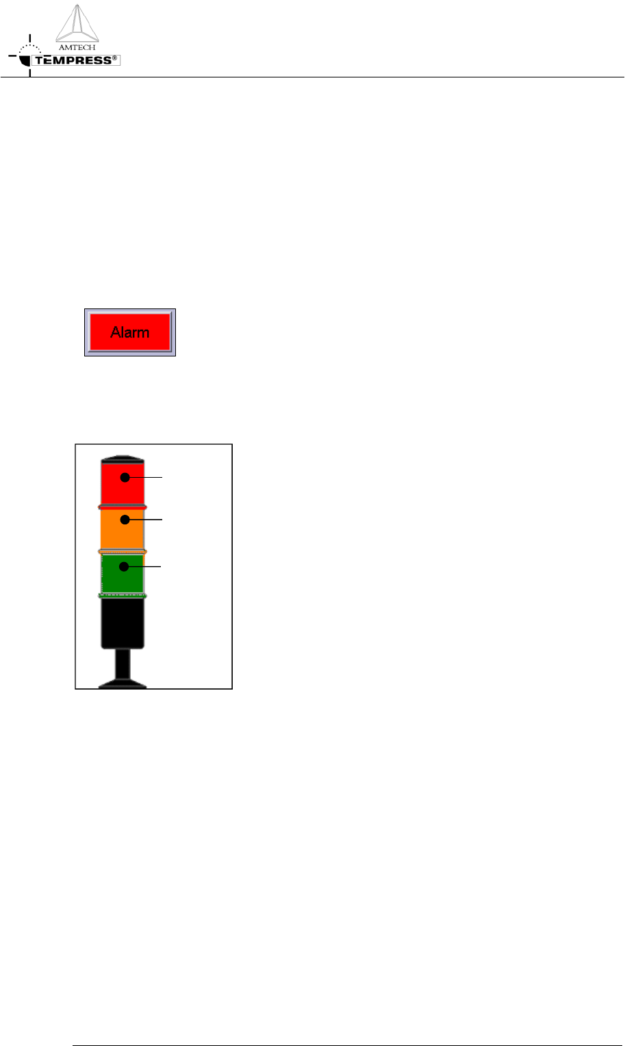
Activating the alarm menu gives an overview of all active and passed
alarms during the process. In case of an active alarm the “Alarm”
button start flashing on and off.
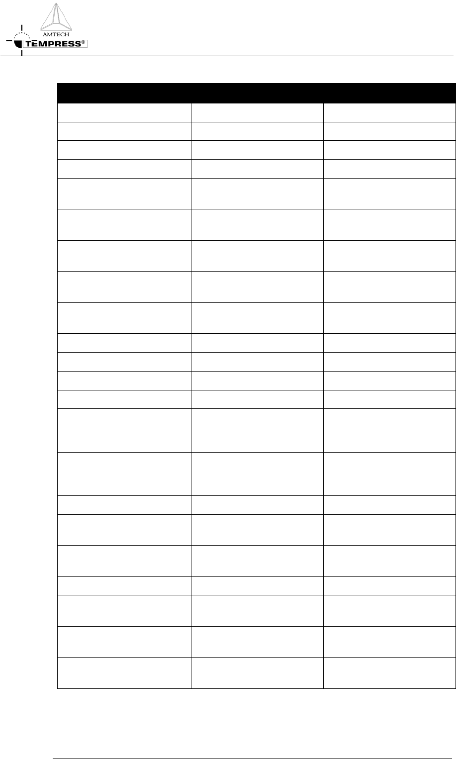
2.3 Light tower signal description
Two light towers, one on top of the loadstation in the
cleanroom and one on top of the furnace in the greyroom, are
installed for fast anticipation on the status of the (production)
process. This section describes the function of each light and its
relation to the tube status.
Red
Y
ellow
Green
A light tower is (default) comprised of 3 lights: from top to
bottom RED, YELLOW and GREEN.
The green light can indicate 2 signals:
1) OFF
2) ON
The yellow and red light can indicate 2 signals:
1) OFF
2) BLINK
Figure 2-1 Default light tower configuration
The light tower is controlled by a tower signal PLC that receives its commands from the
various controllers, among others DPC/DTC/DMC, Excess temperature controller, gas
detection system alarm and the TSC Host control.
In case the EMO-switch is activated or a power failure occurs for more than 4 seconds, the
power supply to the furnace will stop and also the light tower will be off.
The tower signal PLC is programmed by Tempress Systems Inc. and is not adjustable by
customers.
Note: Per tube there are 2 PLC-Inputs available for customer specific applications, like H
2
detection.
2-3
SAFETY
P
ROCESS MANUAL
2-4
For a functional description of the light tower signals see table 1:
Signal Mode Description
Green ON Operational No warnings or messages
OFF Not operational
Yellow BLINKING N
2
pressure-switch No N
2
gas flow detected
Air pressure switch No Air flow detected
Torch temp (750) The torch temperature has
to exceed 750
o
C
Torch Flame failure There is no flame, the H
2
valve will be closed
Torch H
2
/O
2
ratio The H
2
/O
2
ratio exceeds
the safety value
Torch shell The skin temperature of the
torch is too high
Temperature sensor
powerpack
Temperature powerpack is
too high
Bubbler temp Bubbler temp is too high
Bubbler level Fluid level is too low
O
2
- low O
2
flow is too low
Exhaust (Low/High) Exhaust flow out of limits
Limit alarm (only if
programmed in the process
recipe)
Actual value is out of limits
Wait for operator (only if
programmed in the process
recipe)
Operator action is required
to continue
Process is finished
Boat manual Servo driver is in manual
mode
Maintenance mode Maintenance mode is
activated
OFF No alarm and/or alert
Red BLINKING Excess temperature
controller has been activated
Tube is overheated
(Optional) Leakage detection A gas or water leak has been
detected
OFF No alarm and/or alert No actual dangerous or
hazardous situation
Table 1 Light tower signal description