m220_383_02_process_manual工艺手册.pdf.pdf - 第48页
PROCESS DESCRIPTION P ROCESS M ANU AL 4.2-3 Tube Cassettes / baffles SiC paddle Trap (upstream tubing) Oil and filter change Poly 20/100 10 10 - 80
PROCESS DESCRIPTION
P
ROCESS MANUAL
4.2.3
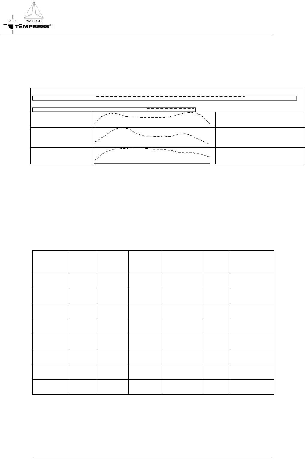
Process result indication
A schematic view of the thickness profile along the load as function of normalized gasflows is
given in the figure below.
Door Pump
A sccm
A sccm
Saddle profile
B sccm
C sccm
D sccm
F sccm
E sccm
The extra injector can also be removed to simplify processing.
4.2.4
Startup parameters for processing
The optical properties of a new and/or cleaned quartz tube change most dramatically after
the first deposition of foreign (=different refractive index) material. For accurate temperature
control a new and/or cleaned tube needs therefore to be coated before any (automatic)
profiling is performed. Use the default process settings for 1 hour to obtain a reasonable
coating.
An oxidized substrate wafer is required to enable accurate measurement, typically 1000Å
thermally oxidized wafers are used.
Type Wafer
Size
[mm]
Process
Time
[min]
Pressure
[mtor]
Thickness
[Å]
Temp.
[
o
C]
SiH
4
[sccm]
TS630x 100
150
30 250 3000 610 30-30-10
TS660x 100
150
30 250 3000 610 40-40-20
TS680x 100
150
30 250 3000 610 60-60-30
TS6100x 100
150
30 250 3000 610 60-60-30
TS840x 150
200
30 250 3000 610 60-60-30
TS860x 150
200
30 250 3000 610 80-80-40
TS8100x 150
200
30 250 3000 610 100-100-50
TS1280x 200
300
30 250 3000 610 200-150-50
4.2.5
Recommended cleaning interval
Cleaning interval for the several components after cumulative deposition in microns on the
wafers.
4.2-2

PROCESS DESCRIPTION
P
ROCESS MANUAL
4.2-3
Tube Cassettes /
baffles
SiC paddle Trap (upstream
tubing)
Oil and filter
change
Poly 20/100 10 10 - 80
PROCESS DESCRIPTION
P
ROCESS MANUAL
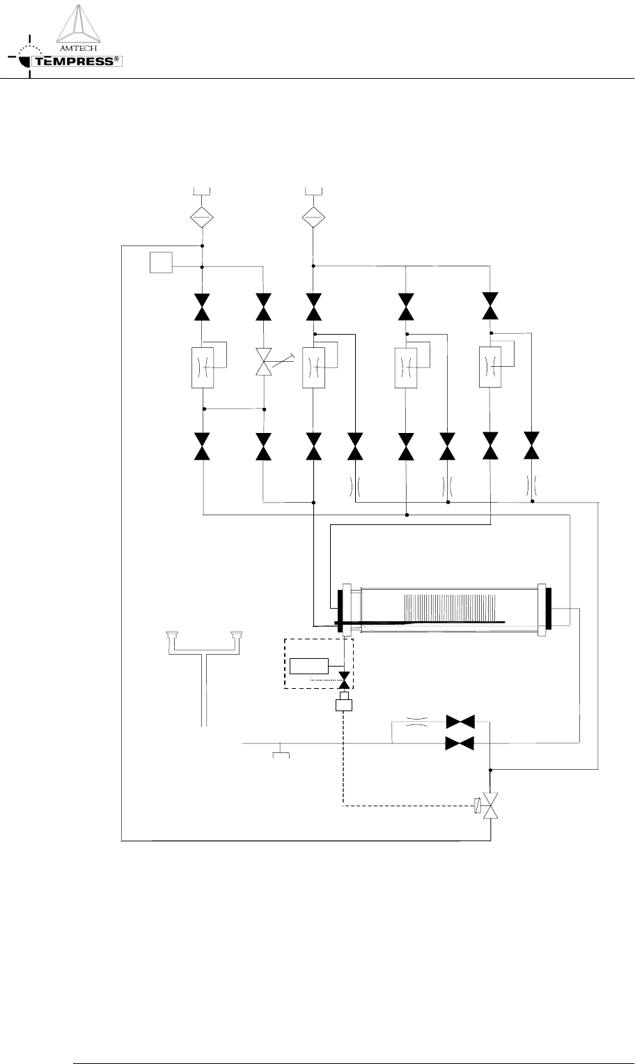
4.2.6
Gas schematic example: LPCVD Flat poly
Injector
Pump exhaust
burn chamber
Vacuum
test port
To pump
Baratron
10T/ATM
option
PS
N
2
SiH
4
4.2-4