m220_383_02_process_manual工艺手册.pdf.pdf - 第55页
PROCESS DESCRIPTION P ROCESS M ANU AL 4.3.2.4 Typicalities The cage design is critical for the cross wafer thickness uniformity, while the injector design and the position of the cage(s) compared to the position of the i…

PROCESS DESCRIPTION
P
ROCESS MANUAL
4.3-1
4.3 Silicondioxide (LTO SiO
2
) from SiH
4
and O
2
4.3.1 Basic configuration
LPCVD Low Temperature Oxide (LTO)
SiH
4
, O
2
, (PH
3
and/or TMB optional)
Injectors are used for SiH
4
+PH
3
+TMB, and for O
2
Flat temperature of 425
o
C
Quartz caged cassettes
4.3.2
Description
4.3.2.1 Purpose
Low Temperature Oxide (LTO) is mainly used as a passivation layer over devices, which
already have metal contacts. Aluminum is widely used but with melting point of roughly
600
o
C a passivation layer deposition technique with a deposition temperature higher than the
aluminum melting point is not possible.
LTO is used to create a passivation layer while maintaining the aluminum contact integrity.
The low temperature reduces the electrical and mechanical properties of the deposited SiO
2
film, which makes it typically unsuitable for electrical applications.
4.3.2.2 Chemicals
Oxygen is the basic gas of every combustion reaction and therefore leaks can be dangerous
near hot areas.
SiH
4
is a pyrogenic gas, which means it will burn spontaneously when it comes into contact
with O
2
or air. It is also toxic and should be handled accordingly, although generally it will
burn before it gets toxic.
4.3.2.3 Process
Due to the pyrophoric nature of SiH4 combining SiH
4
and O
2
to do a process requires a
distinct handling procedure. This includes reduction of the process pressure and applying a
specific gas distribution system.
The deposition of LTO from SiH
4
and O
2
is a very physical process. This means, the
deposition rate strongly depends on the gas flows and diffusion properties. The gas flow is
mainly affected by the hardware configuration and not so much by the temperature. The
result is, that the deposition rate and thickness uniformity do not react much on temperature
changes, but do react on hardware changes such as cage and injector design, position of these
in view of each other, injector alignment and wafer alignment.
Additionally, as with most LPCVD processes, the pressure will also affect the process results.
The chemical reaction of a basic LTO process is as follows:
SiH
4
+ O
2
Æ SiO
2
+ 2 H
2

PROCESS DESCRIPTION
P
ROCESS MANUAL
4.3.2.4 Typicalities
The cage design is critical for the cross wafer thickness uniformity, while the injector design
and the position of the cage(s) compared to the position of the injector holes are critical for
the cross load uniformity. If the cross wafer uniformity is above 5% a new cage design is
required.
The cage(s) almost fully cover the holes of the injector. In other words, the holes are
distributed in between the first and last cage. Note that the front of the cages is leaded by 1 or
2 holes to get sufficient SiH
4
before the cages.
The O
2
and SiH
4
injectors should be aligned as indicated in the following picture:
O
2
injector SiH
4
injector
If the gas entry mounting points are mirrored also the injector alignment should be mirrored,
the O
2
should mix in the SiH
4
stream.
For O
2
one or two extra holes are added at the door side.
If strong depletion is observed and the cross load uniformity is not improving some N
2
can
be added to the SiH
4
injector.
The pressure should be kept as low as possible while maintaining an acceptable deposition
rate. Decreasing the pressure will improve cross load uniformity some and reduce the
deposition rate.
The temperature is not an important parameter, a temperature ramp of +- 10 to 20
o
C is
typical but has limited effect.
4.3.3
Startup parameters for processing
Type Wafer
Size
[mm]
Process
Time
[min]
Pressure
[mtor]
Thickness
[Å]
Temp.
[
o
C]
SiH
4
[sccm]
O
2
[sccm]
N
2
[sccm]
TS630x 100
150
30 200 2000 425 30 90 500
TS660x 100
150
30 200 2000 425 40 120 500
TS680x 100
150
30 200 2000 425 50 150 500
TS6100x 100
150
30 200 2000 425 70 200 500
4.3.4
Recommended cleaning interval
Cleaning interval for the several components after cumulative deposition in microns on the
wafers.
Tube Cassettes /
baffles
SiC paddle Trap (upstream
tubing)
Oil and filter
change
LTO 20 10 10 10 50
4.3-2
PROCESS DESCRIPTION
P
ROCESS MANUAL
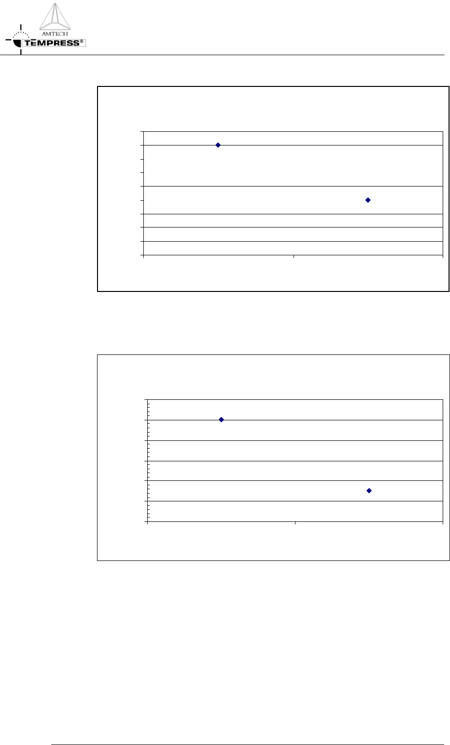
LTO process results (1)
cage design effect
0.0
0.5
1.0
1.5
2.0
2.5
3.0
3.5
4.0
4.5
cage 1 cage 2
cage design
cross wafer uniformity [%]
4.3.5 Process result indication
LTO process results (2)
injector design effect
0.0
2.0
4.0
6.0
8.0
10.0
12.0
injector 1 injector 2
injector design
cross load uniformity [%
]
4.3-3