m220_383_02_process_manual工艺手册.pdf.pdf - 第82页
OPERATION INSTRUCTIONS P ROCESS M ANU AL 5) select SCREEN to find the desired screen number (max 4) 6) define the tu be configuration (Left or Right) and the am ount of heating zones first 7) select L for Door on Left, s…
OPERATION INSTRUCTIONS
P
ROCESS MANUAL
5.10 Edit graphical image
To support the process recipe and to give actual progress information during the process run
a graphical representation of the tube and its components can be added to the process
certifications.
The touchscreen allows predefined symbols and locations only, TSC-2 allows total freedom
for the graphical operations screen layout.
Note: For accurate representation keep the process gas schematic at hand.
5.10.1
Touchscreen
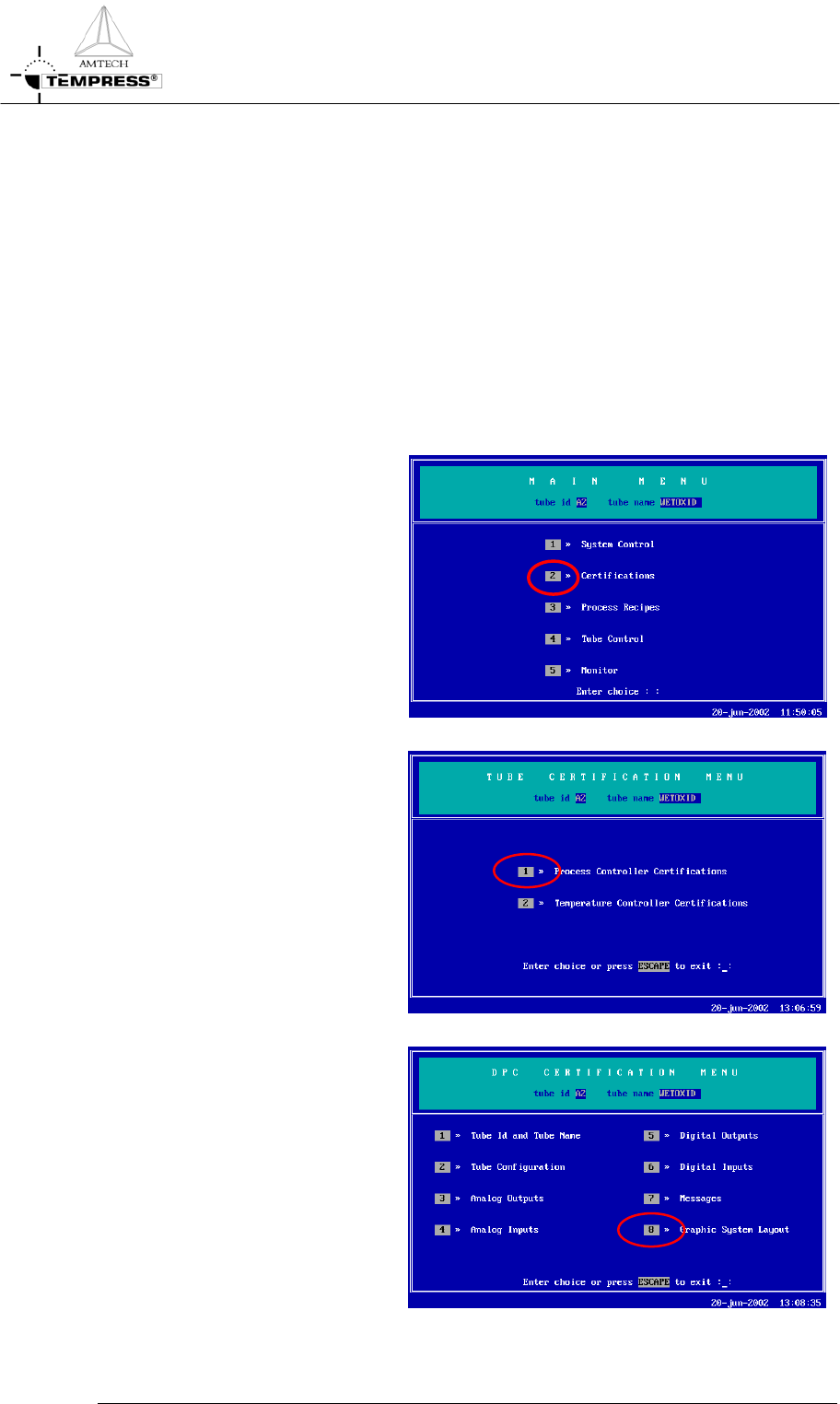
1) return to the Main Menu by
pressing ‘ESC’ until the
following screen appears:
2) press ‘2’ to access ‘Tube
Certifications’
3) press ‘1’ to access ‘Process
Controller Certifications’
5.10-2
4) press ‘8’ to access ‘Graphic
System Layout’
OPERATION INSTRUCTIONS
P
ROCESS MANUAL
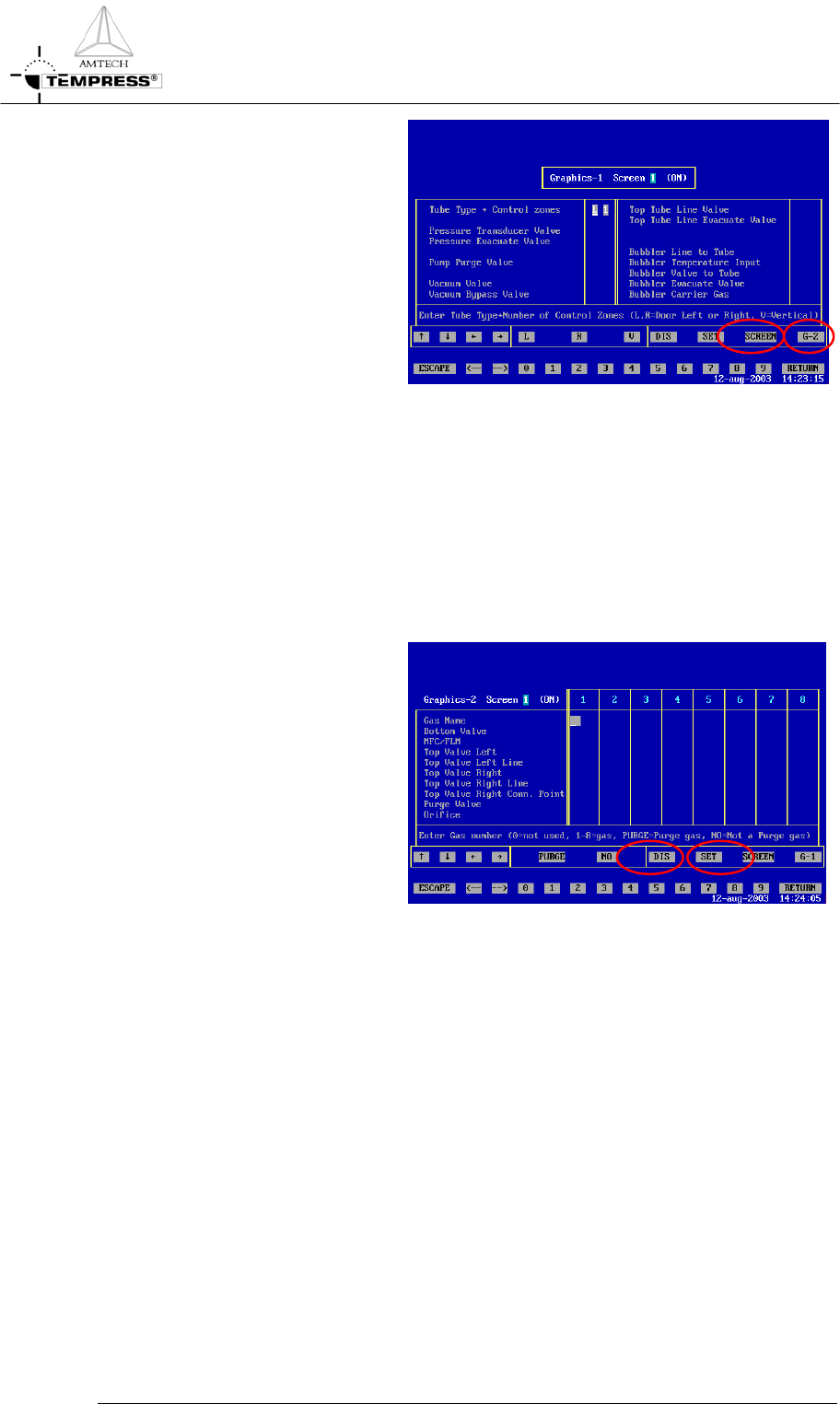
5) select SCREEN to find the
desired screen number (max 4)
6) define the tube configuration
(Left or Right) and the amount
of heating zones first
7) select L for Door on Left, select
R for Door on Right
8) select the number of heating
zones by pressing the correct
number (typically 3 or 5). Press
RETURN to confirm.
9) for LPCVD tubes define the
Pressure Transducer valve up to
the Top Tube Line Evacuate
Valve if applicable. Select the
appropriate Digital Output
number (DOx)
10) select G-2 to access the second
part of the graphical system
layout
11) select the appropriate gas
number (Analog Output
number) to place the
corresponding gasline in the
desired column 1-8
12) select Purge or No purge
(default) to define its use for the
gasline if applicable
13) select Bottom and/or Top valve
+ MFC or FLM to match the
appropriate DOx numbers
14) select Top Valve Left Line
and/or Top Valve Right Line
and connect them to 1 out of 4
possible horizontal gaslines
15) select the appropriate purge
valve DOx and/or orifice if
applicable
5.10-3

OPERATION INSTRUCTIONS
P
ROCESS MANUAL
16) select DIS to test the graphical
system layout
17) select SET to activate the
selected screen
5.10-4