00198365-03_UM_JTF-ML2_TX12_V1-V2_EN - 第21页
2 Operational safety 2.4 ESD guidelines User Manual SIPLACE TX V1/V2 Series JEDEC Tray Feeder (JTF-ML2) 11/2019 21 2.4 ESD guidelines 2.4.1 What does ESD mean? Fig.15: ESD label Almost all of the modules in use today ar…
2 Operational safety
2.3 Safety features
20 User Manual SIPLACE TX V1/V2 Series JEDEC Tray Feeder (JTF-ML2) 11/2019
2.3 Safety features
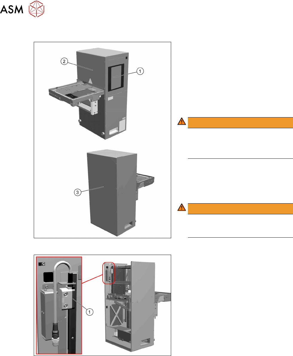
Fig.13: Door and covers
To prevent injuries, there are one door and
various safety covers attached to the
SIPLACE JTF‑ML2.
The door(1) on the SIPLACE JTF‑ML2 is
locked during operation.
When the cassettes need to be changed,
the door can be unlocked using the station
software. The SIPLACE JTF-ML2 is inactive
then and all motors are stopped.
WARNING!
Door
It is not allowed to operate the
SIPLACE JTF‑ML2 without or with
open door.
.
The SIPLACE JTF-ML2 has several covers.
Do not remove these.
(2) Front cover
(3) Back and top cover
WARNING!
Covers
It is not allowed to operate the
SIPLACE JTF-ML2 without covers.
.
Fig.14: Safety protective switch and actuator
Safety protective switch and actuator (1)
This switch is to monitor safety loop signal
from TX machine and detect opening of the
door. If either signal is opened, door switch
contact will be opened and de-energized
safety relay output. Power supply to all mo-
tors will be cut-off.
2 Operational safety
2.4 ESD guidelines
User Manual SIPLACE TX V1/V2 Series JEDEC Tray Feeder (JTF-ML2) 11/2019 21
2.4 ESD guidelines
2.4.1 What does ESD mean?
Fig.15: ESD label
Almost all of the modules in use today are equipped with highly integ-
rated Metal-Oxide-Semiconductor (MOS) blocks and components.
The manufacturing techniques used mean that these electronic com-
ponents are extremely sensitive to overvoltage and thus to electro-
static discharge.
The abbreviation for such modules is "ESD" (Electrostatic Sensitive
Device). "ESD" is used internationally. The following symbol on cab-
inet rating plates, racks or packaging indicates that components
which are sensitive to electrostatic discharge have been used and
thus that the modules concerned are also touch-sensitive.
ESDs can be destroyed by voltages and power levels that are far below the level that can be per-
ceived by humans. Such voltages occur if a person touches a component or module without
earthing themselves. Components that are exposed to such overvoltages do not generally appear
to be defective immediately - incorrect behavior starts after the component or module has been in
operation for some time.
2.4.2 Important measures to protect against static charging
► Most plastics can easily become charged and must therefore be kept away from at-risk com-
ponents.
► Always ensure that people, the workplace and packaging are safely earthed when handling
electrostatic sensitive components.
2.4.3 Handling ESD modules
As a general rule: Only touch electronic modules if you must carry out work on the modules. In that
case, make sure that you do not touch the pins or printed conductors when you pick up flat mod-
ules.
Only touch components if you are earthed by one of the following measures:
●
You are wearing an ESD wristband.
●
You are wearing ESD shoes.
●
You are wearing ESD shoe earthing strips on an ESD floor.
Immediately before you touch an electronic module, discharge your own body by touching a con-
ductive and earthed object (such as unpainted parts of a switch cabinet, a water pipe, etc.).
Do not allow modules with chargeable and highly insulating materials to touch one another, e.g.
plastic films, insulating table surfaces or items of clothing made from synthetic fibers.
Always place the modules on a conductive surface (table with an ESD coating, conductive ESD
foam, ESD bag or container).
Do not move the assemblies near to data view devices, monitors or television units. Keep a min-
imum distance of 10 cm to monitors.
2.4.4 Measurements and modifications to ESD modules
Only perform measurements on modules if one of the following conditions is fulfilled:
●
You are using an earthed measuring device (e.g. via PE conductors)
●
You are using a potential-free measuring device and discharge the measuring head before
the measurement (e.g.by touching an unpainted metal part of the controller casing).
► Always use an earthed soldering iron if you carry out any soldering work.
2 Operational safety
2.5 FCC, RFID
22 User Manual SIPLACE TX V1/V2 Series JEDEC Tray Feeder (JTF-ML2) 11/2019
2.4.5 Dispatching ESD modules
► Always store modules and components in conductive packaging (e.g. metallized plastic bags
or metal sleeves) and dispatch them in conductive packaging
► If the packaging is not conductive, place the modules in a conductive envelope before pack-
aging. Use conductive expanded rubber, ESD bags, domestic aluminum foil or paper, for
example. NEVER use plastic bags or film.
► If the module has integral batteries, ensure that the conductive packaging does not touch or
short circuit the battery terminals and, if necessary, first cover the terminals with insulating
tape or material.
2.5 FCC, RFID
2.5.1 FCC Caution
Any changes or modifications not expressly approved by the party responsible for compliance
could void the user's authority to operate this equipment. This device complies with Part 15 of the
FCC Rules. Operation is subject to the following two conditions:
1. This device may not cause harmful interference, and
2. This device must accept any interference received, including interference that may cause
undesired operation.
NOTICE
This equipment has been tested and found to comply with the limits for a Class B digital
device, pursuant to part 15 of the FCC Rules. These limits are designed to provide
reasonable protection against harmful interference in a residential installation. This
equipment generates, uses and can radiate radio frequency energy and, if not installed and
used in accordance with the instructions, may cause harmful interference to radio
communications. However, there is no guarantee that interference will not occur in a
particular installation. If this equipment does cause harmful interference to radio or
television reception, which can be determined by turning the equipment off and on, the user
is encouraged to try to correct the interference by one or more of the following measures:
► Reorient or relocate the receiving antenna.
► Increase the separation between the equipment and receiver.
► Connect the equipment into an outlet on a circuit different from that to which the recei-
ver is connected.
► Consult the dealer or an experienced radio/TV technician for help.
2.5.2 RFID on SIPLACE JTF-ML2
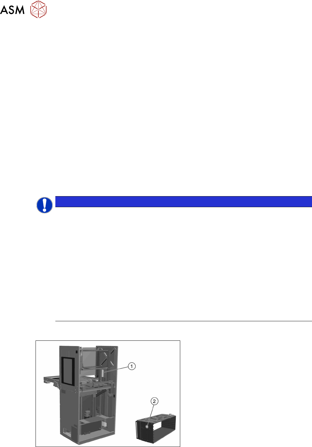
Fig.16: RFID on SIPLACE JTF-ML2
1. The RFID reader module is located in
the tower of the SIPLACE JTF‑ML2.
2. One RFID tag is located on each
SIPLACE JTF‑ML2 cassette.