00198365-03_UM_JTF-ML2_TX12_V1-V2_EN - 第34页
4 Setting up and commissioning 4.2 Retrofitting in the SIPLACE TX-Series 34 User Manual SIPLACE TX V1/V2 Series JEDEC Tray Feeder (JTF-ML2) 11/2019 4.2.5 Performing retrofitting 4.2.5.1 Preparatory steps ► Move the compo…
4 Setting up and commissioning
4.2 Retrofitting in the SIPLACE TX-Series
User Manual SIPLACE TX V1/V2 Series JEDEC Tray Feeder (JTF-ML2) 11/2019 33
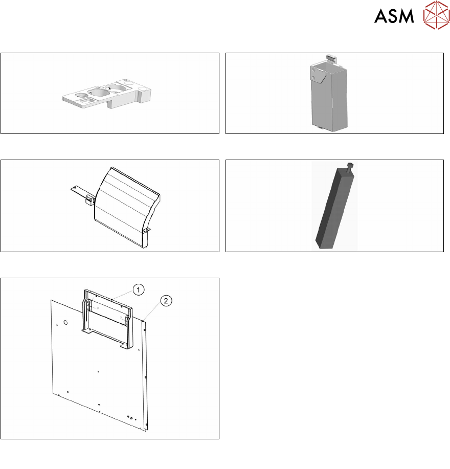
Fig.36: Nozzle station. IC camera V2 (optional)
Fig.37: Reject box
Fig.38: Empty tape duct, short SIPLACE TX assembly
Fig.39: Mounting support SIPLACE TX-JTF assembly
Fig.40: Cover assembly for SIPLACE JTF-ML/ML2 com-
plete
Cover assembly for SIPLACE JTF-ML/ML2
complete
Consists of:
1. Support frame assembly location 1 for
SIPLACE JTF-ML/ML2 complete
2. Cover assembly on output side location 1,
TX
4.2.3 Tools and equipment required
●
Standard tools
●
Recommended: Allen key extension, ratchet
●
Hammer
●
Punch
●
Feeler gauge
●
Belt tension measuring device [00326015‑xx]
●
Ethanol
Isopropanol – IPA can be used as an alternative.
●
Lint-free cleaning cloths [03082092‑xx]
●
Lifting trolley
●
Second person
●
Assembly instructions "Input and Output Conveyor Extension SIPLACE TX" [00198141‑xx]
4.2.4 Required working time
The complete installation, including the output conveyor extension, will take approx. four hours.
4 Setting up and commissioning
4.2 Retrofitting in the SIPLACE TX-Series
34 User Manual SIPLACE TX V1/V2 Series JEDEC Tray Feeder (JTF-ML2) 11/2019
4.2.5 Performing retrofitting
4.2.5.1 Preparatory steps
► Move the component trolleys out of the machine.
► Switch off the machine, disconnect it from the power supply and secure it to prevent
unauthorized reactivation.
4.2.5.2 Converting the COT insert for the SIPLACE TX
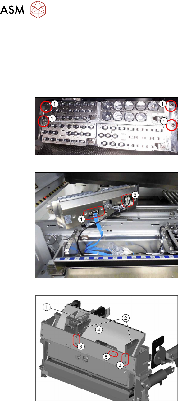
Fig.41: Removing NC 1
► Remove the four screws(1) fastening
the nozzle changer (NC).
Fig.42: Removing NC 2
► Unplug the electrical(1) and pneumatic
connections(2) for the nozzle changer
and put the NC aside.
Fig.43: Removing the NC holder
► Remove the reject bin(1).
► To remove the empty tape duct (4)
remove the screws(3) fastening the
two NC holders(2) and remove the NC
holders.
(The screw holes marked with (5) will be
used for the holder of the big reject bin later
on)
4 Setting up and commissioning
4.2 Retrofitting in the SIPLACE TX-Series
User Manual SIPLACE TX V1/V2 Series JEDEC Tray Feeder (JTF-ML2) 11/2019 35
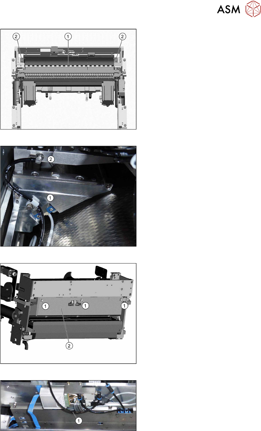
Fig.44: Removing the empty tape duct
► Remove the two screws (2) holding the
empty tape duct (1).
► Carefully lift the empty tape duct out of
the COT insert.
Fig.45: Dismantling the sensor
► Dismantle the sensor(1) on the right
NC holder.
► Dismantle the vacuum hose and extend
it with the adapter assembly nozzle sta-
tion TX V2 [03169973—xx] (2).
► This is necessary if a CPP head and
the big reject bin with nozzle station are
installed.
Fig.46: Dismantling the rear cover
► Remove the three screws(1) fastening
the rear cover(2).
Now, you can move the cover a bit to the
side and lift it off. Thus, it is easier to thread
the sensor cable.
Fig.47: Converting the sensor
► Push the sensor through the open-
ing(1) on the front cover.