00198365-03_UM_JTF-ML2_TX12_V1-V2_EN - 第39页
4 Setting up and commissioning 4.2 Retrofitting in the SIPLACE TX-Series User Manual SIPLACE TX V1/V2 Series JEDEC Tray Feeder (JTF-ML2) 11/2019 39 Fig.56: Fitting the reject bin holder ► Fit the reject bin holder with …
4 Setting up and commissioning
4.2 Retrofitting in the SIPLACE TX-Series
38 User Manual SIPLACE TX V1/V2 Series JEDEC Tray Feeder (JTF-ML2) 11/2019
Fig.54: Fitting the holder
► Fit the holder(2), using the two screws
ISO4762-M6x14-A2-70 [03043125‑xx]
provided, to the traverse bar(1).
When tightening the screws, press the
holder upwards, against the edge(3).
Fitting the reject bin holder with nozzle station for the SIPLACE TX Series V2
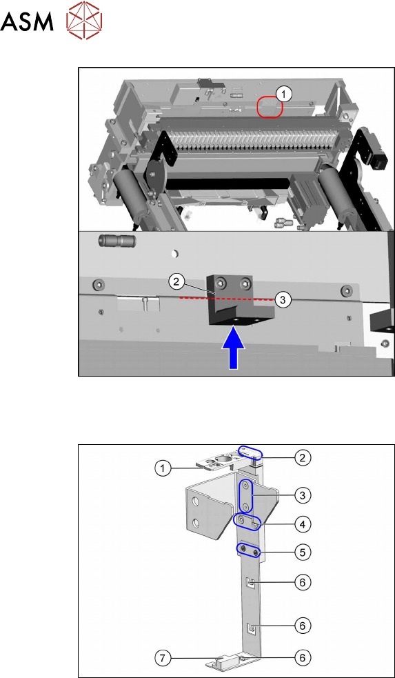
Fig.55: Fitting the reject bin holder
1. Nozzle station [03106821‑xx]
The nozzle station is fitted after meas-
uring the height.
2. Fastening screws of the nozzle station
[00333782‑xx]
3. Fastening screws for retaining bracket
ISO10642-M5x10-A2-70 [03082832‑xx]
4. Fastening screws of the complete
holder on the COT insert DIN7984-
M6x12-A2-70 [03081847‑xx]
5. Fastening screws ISO 7380-2 M 3 x 6-
A2-70 [03099571-xx], only for setting
the sensor height
6. Three lugs for cable ties
7. Sensor [03088550‑xx]
The sensor that is already installed and
cabled on the insert is used.
► Fit the individual parts of the reject bin holder.
► Use the cable ties to fix the sensor to the three lugs.
4 Setting up and commissioning
4.2 Retrofitting in the SIPLACE TX-Series
User Manual SIPLACE TX V1/V2 Series JEDEC Tray Feeder (JTF-ML2) 11/2019 39
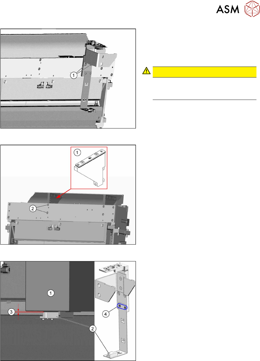
Fig.56: Fitting the reject bin holder
► Fit the reject bin holder with two fasten-
ing screws DIN7984-M6x12-A2-70
[03081847-xx](1) on the COT insert.
Push the sensor cable behind the cover
as far as possible.
CAUTION!
If too much cable length lies in front of
the cover, the reject bin may damage
the cable.
.
Fig.57: Fitting the NC holder
► Fit the right NC holder(1) with two
fastening screws DIN 7984-M6 x 12-
A2-70 [03081847-xx](2). The right NC
holder is replaced by the supplied ver-
sion without nozzle station.
Do not fit the NC and the nozzle station yet!
Fig.58: Setting the sensor
1. Reject box
2. Sensor
3. Distance 2.0+/-1.0mm
4. Fastening screws for setting the senor
height
► Insert the reject bin.
► Set the sensor to a distance of
2.0+/-1.0mm from the reject bin.
4 Setting up and commissioning
4.2 Retrofitting in the SIPLACE TX-Series
40 User Manual SIPLACE TX V1/V2 Series JEDEC Tray Feeder (JTF-ML2) 11/2019
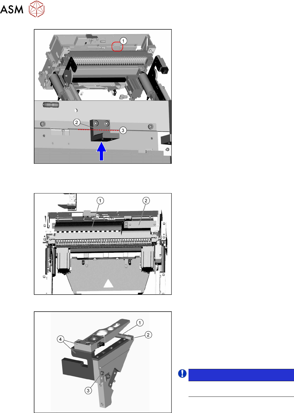
Fig.59: Fitting the holder
► Fit the holder(2), using the two screws
ISO4762-M6x14-A2-70 [03043125‑xx]
provided, to the traverse bar(1).
When tightening the screws, press the
holder upwards, against the edge(3).
Fitting the empty tape duct and removing the nozzle changer
Fig.60: Fitting the empty tape duct and cover
► Fit the short empty tape duct(1), using
two ISO4762-M6x14-A2-70
[03043125‑xx] screws.
► Fit the "hand guard tape cutter"(2)
[03130649‑xx] with two screws
ISO4762-M6x14-A2-70 [03043125‑xx].
Fig.61: Removing the NC holder
Perform the following steps on the dis-
mantled NC holder:
► Remove the screw(2) fastening the
support(1) and remove this.
► Remove the screw(3) fastening the
nozzle station and the reject bin
holder(4) and remove this.
NOTICE!
The previously used nozzle station is
no longer needed.
.
► Close open pneumatic connections if
necessary.