00198365-03_UM_JTF-ML2_TX12_V1-V2_EN - 第52页
4 Setting up and commissioning 4.2 Retrofitting in the SIPLACE TX-Series 52 User Manual SIPLACE TX V1/V2 Series JEDEC Tray Feeder (JTF-ML2) 11/2019 Fig.91: Wiring the SIPLACE JTF-ML2 at SIPLACE TX series V1 – part 1
4 Setting up and commissioning
4.2 Retrofitting in the SIPLACE TX-Series
User Manual SIPLACE TX V1/V2 Series JEDEC Tray Feeder (JTF-ML2) 11/2019 51
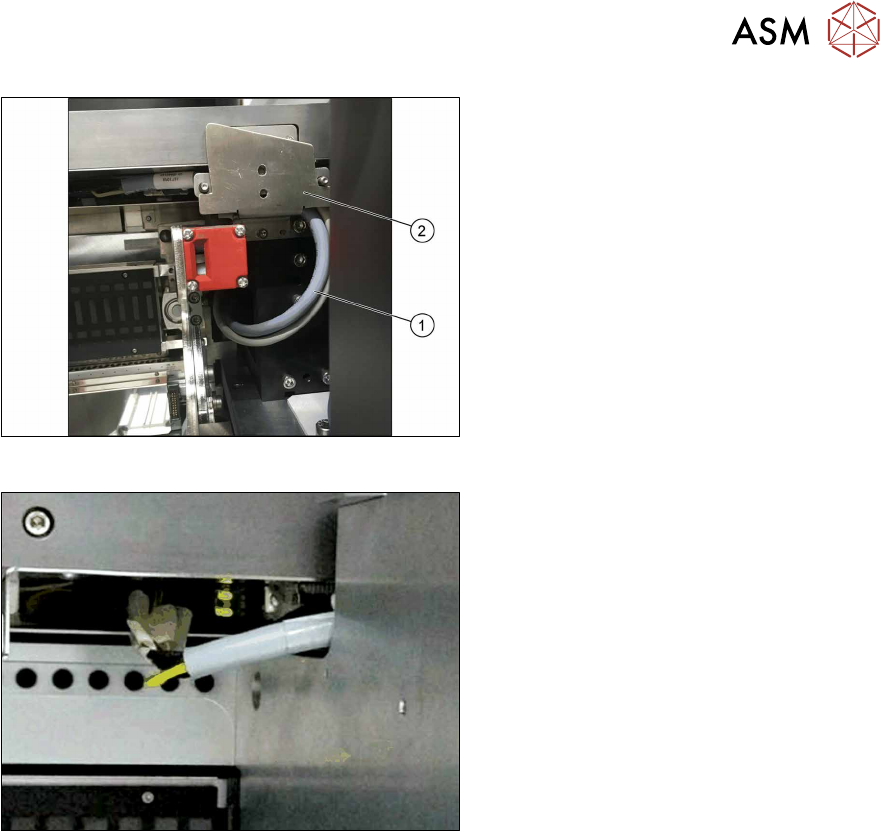
Fig.89: Cable routing
► Pay attention to the correct running of
the cables [03134469‑xx] and
[03134468‑xx](1) at the conveyor. The
cables have to be in the mounting
bracket(2).
Fig.90: Cable with docked COT
► Make sure there is a gap between the
cable and the COT to avoid cable rub-
bing during insertion or removal of
COT.
► Run the cables below the conveyor of the SIPLACE JTF‑ML2 towards the back of the COT insert.
► Connect the CAN bus cable [03134468‑xx] to connector X17 at the FCU.
► Locate the connectors X1.JTF and X4.COTi1 in the machine base.
► Connect the power cable [03134469‑xx] to connectors X1.JTF and X4.COTi1 at the cable har-
ness. If necessary also use adapter cable [03160347‑xx].
4 Setting up and commissioning
4.2 Retrofitting in the SIPLACE TX-Series
52 User Manual SIPLACE TX V1/V2 Series JEDEC Tray Feeder (JTF-ML2) 11/2019
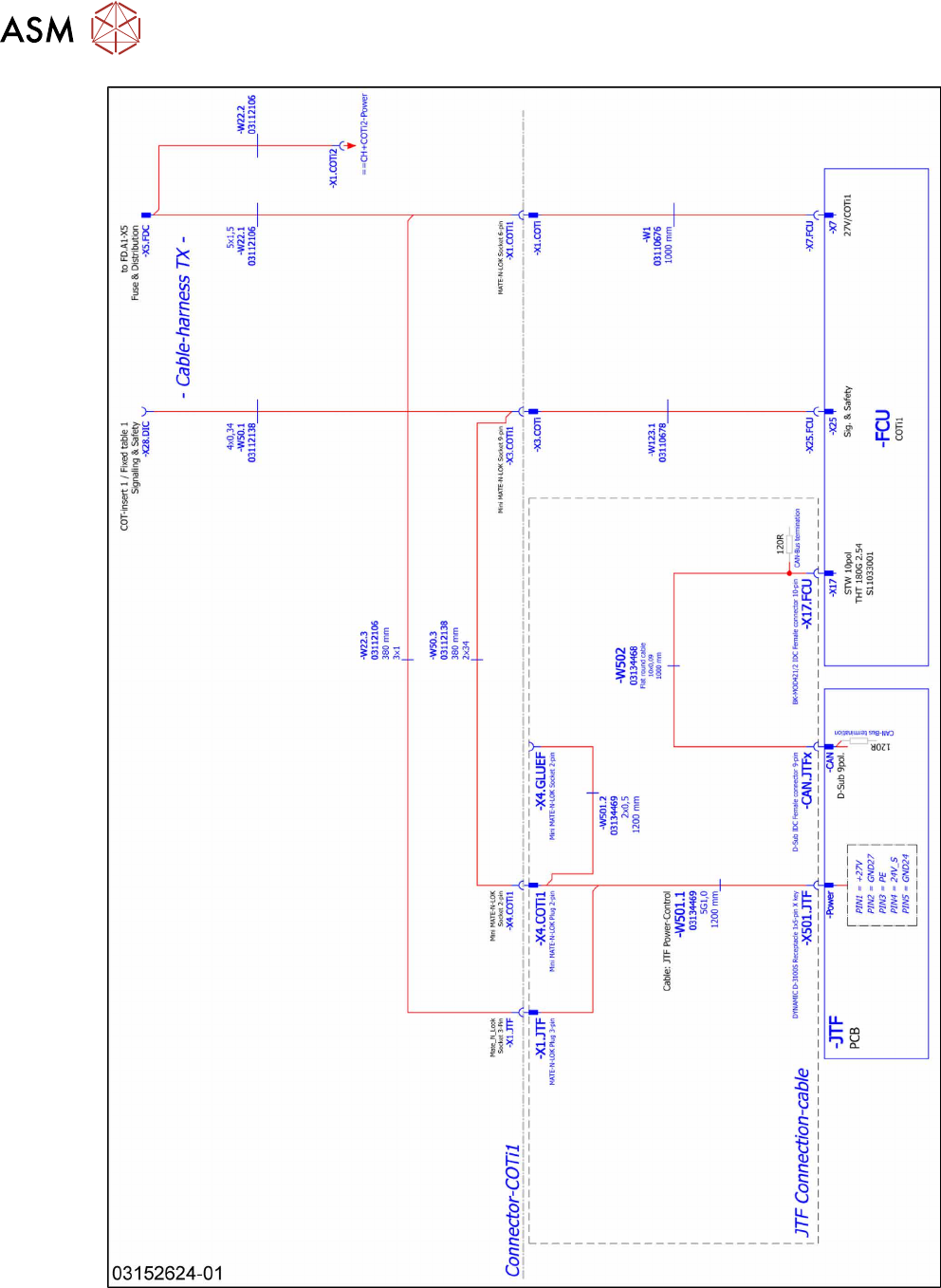
Fig.91: Wiring the SIPLACE JTF-ML2 at SIPLACE TX series V1 – part 1
4 Setting up and commissioning
4.2 Retrofitting in the SIPLACE TX-Series
User Manual SIPLACE TX V1/V2 Series JEDEC Tray Feeder (JTF-ML2) 11/2019 53
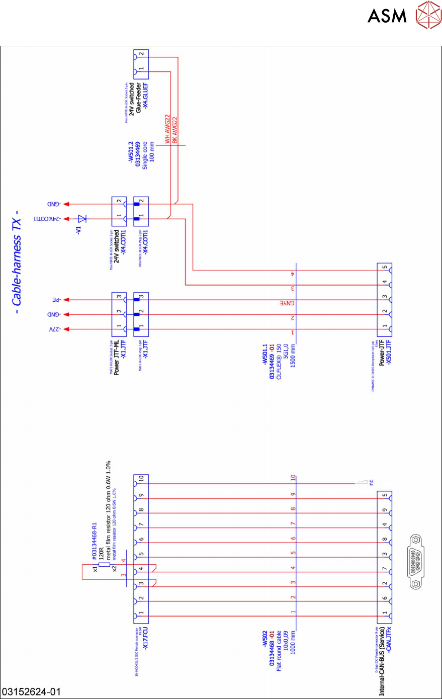
Fig.92: Wiring the SIPLACE JTF-ML2 at SIPLACE TX series V1 – part 2