00198365-03_UM_JTF-ML2_TX12_V1-V2_EN - 第85页
7 Appendix 7.1 Excerpts from the Service Manual User Manual SIPLACE TX V1/V2 Series JEDEC Tray Feeder (JTF-ML2) 11/2019 85 7 Appendix For the settings and calibration of the nozzle changer and nozzle station as well as r…

6 Maintenance
6.1 Overview maintenance tasks
84 User Manual SIPLACE TX V1/V2 Series JEDEC Tray Feeder (JTF-ML2) 11/2019
7 Appendix
7.1 Excerpts from the Service Manual
User Manual SIPLACE TX V1/V2 Series JEDEC Tray Feeder (JTF-ML2) 11/2019 85
7 Appendix
For the settings and calibration of the nozzle changer and nozzle station as well as removal and
connections of the FCU, use the relevant service manuals.
7.1 Excerpts from the Service Manual
The following chapters are excerpts from the service manual for your machine. If required, further
information is provided there.
●
Service manual SIPLACE TX-Series V1 [DE:00198149‑xx] [EN:00198150‑xx]
●
Service manual SIPLACE TX-Series V2 [DE:00198538‑xx] [EN:00198539‑xx]
7.1.1 Replacing the Feeder Control Unit (FCU)
Parts, Equipment and Tools
●
X-FCU V2, TX-/X-Series [03096377-xx]
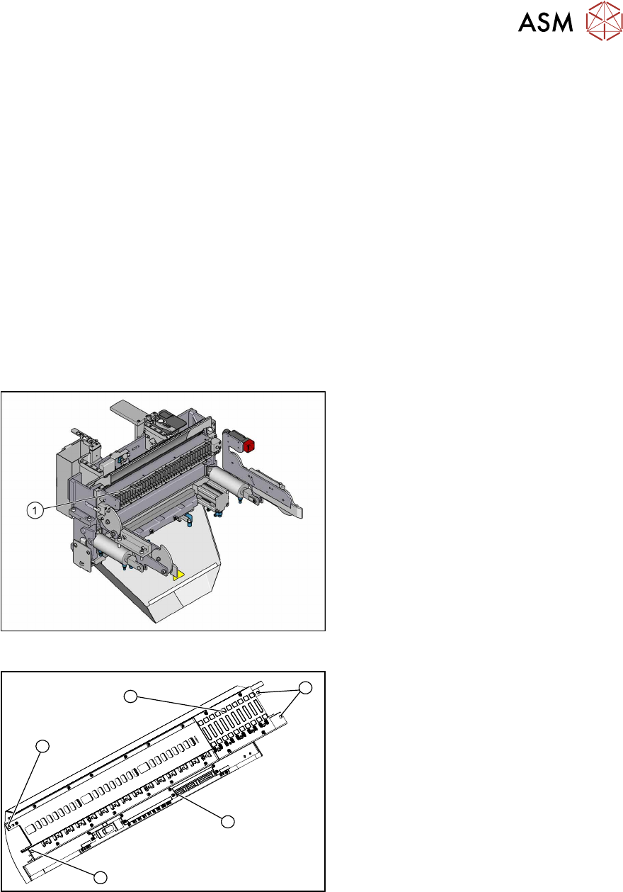
Overview
Fig.153: FCU on COTi
1. Feeder control unit
The feeder control unit is installed at the loc-
ations in the COTi.
3
3
1
3
2
Fig.154: FCU overview
1. FCU assembly
2. Terminal strip
3. Screws fastening the FCU
Depending on the version, there will be
four or six screws.
Removal
► Switch off the machine, disconnect it from the power supply and secure it to prevent
unauthorized reactivation.
► Remove the feeder unlocking device.
7 Appendix
7.1 Excerpts from the Service Manual
86 User Manual SIPLACE TX V1/V2 Series JEDEC Tray Feeder (JTF-ML2) 11/2019
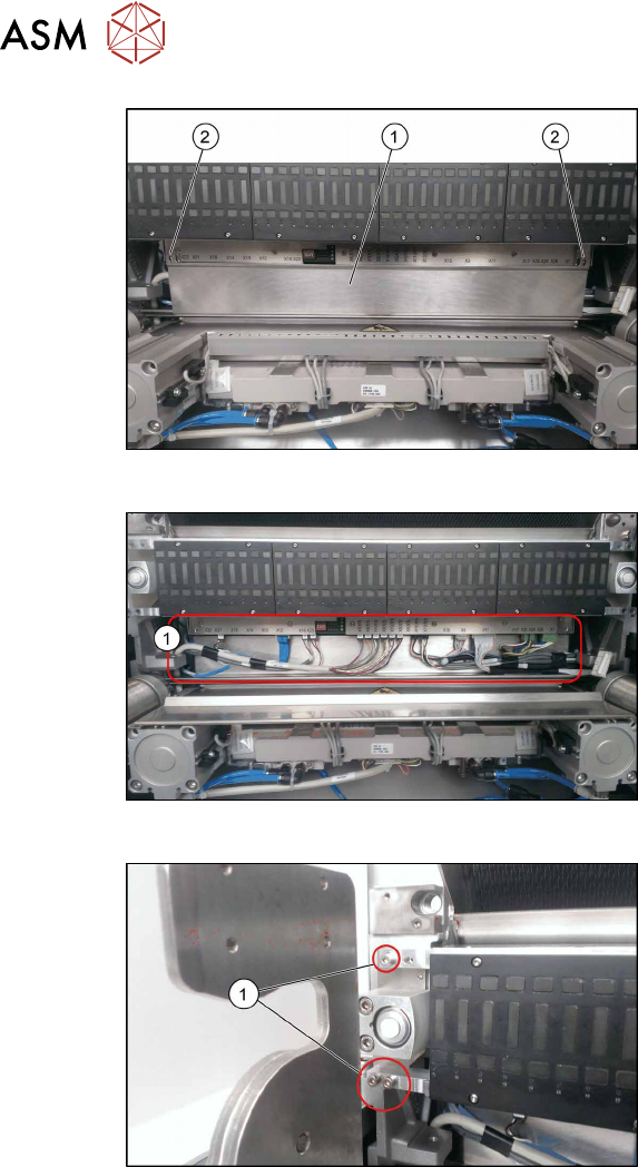
Fig.155: FCU cover plate
► Remove the two fixing screws(2) of the
FCU cover plate(1).
Fig.156: Connections
► Unplug all electrical connections from
the terminal strip of the FCU.
Fig.157: Fixing Screws
► Remove the screws fastening the
FCU(1) on both sides.
Depending on the version, there will be
four or six screws.
► Carefully lever the FCU out of the locating pins.
► Remove the earth terminal.
Installation
► Set the DIP switches on the FCU.
7.1.1.1 "Board description Feeder Control Unit (FCU)" [}87]
► Refit the cover plate and the FCU.
► Place the connection cable in the recess and carefully push in the new FCU. Make sure you
do not pinch any cables.
► Pull the ends of the cables out from under the terminal strip.
► Plug in all electrical connections as labeled on the terminal strip.
► Further installation is performed by following the above instructions in the reverse order.