00198352-01_AI_Conveyor_Conversion_Kit_E-by-SIPLACE_EN - 第17页
Assembly Instructions E by SIPLACE Conveyor Conversion Kit 03/2017 2 Conversion 2.3 Steps and procedure 17 Fig.7: Stopper rail screws ► Remove the cable ties that fix the stopper rail cables. ► Remove the stopper rail s…
2 Conversion
2.3 Steps and procedure
Assembly Instructions E by SIPLACE
Conveyor Conversion Kit 03/2017
16
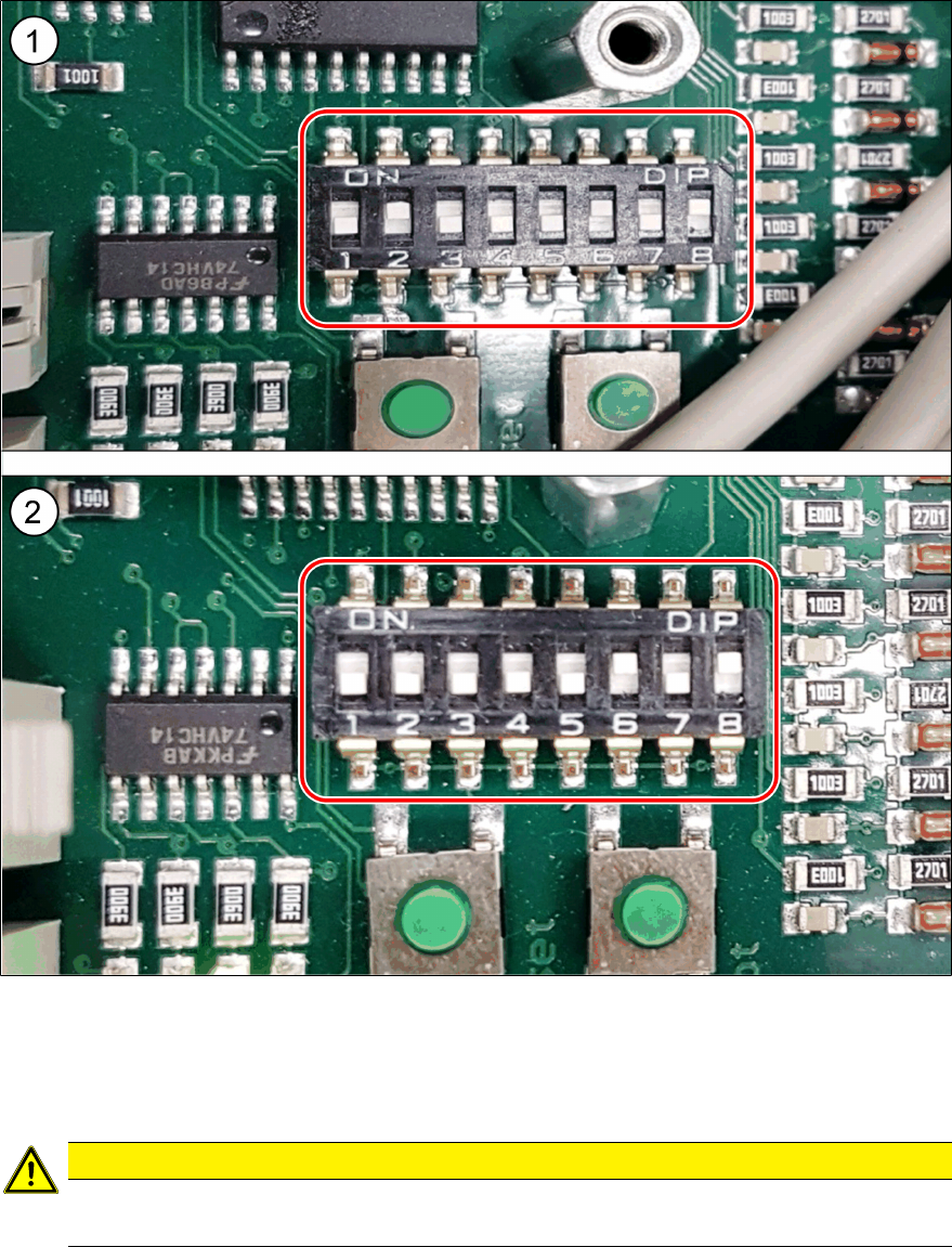
Fig.6: Dip switch for left and right fixed conveyor
1 Picture of left fixed conveyor TSP400
dip switch setting
→ set pin 2, 6 and 8 ON
2 Picture of right fixed conveyor TSP400
dip switch setting
→ set pin 6 and 8 ON
CAUTION
Important Setting!
► Set the dip switch for your conveyor type.
Assembly Instructions E by SIPLACE
Conveyor Conversion Kit 03/2017
2 Conversion
2.3 Steps and procedure
17
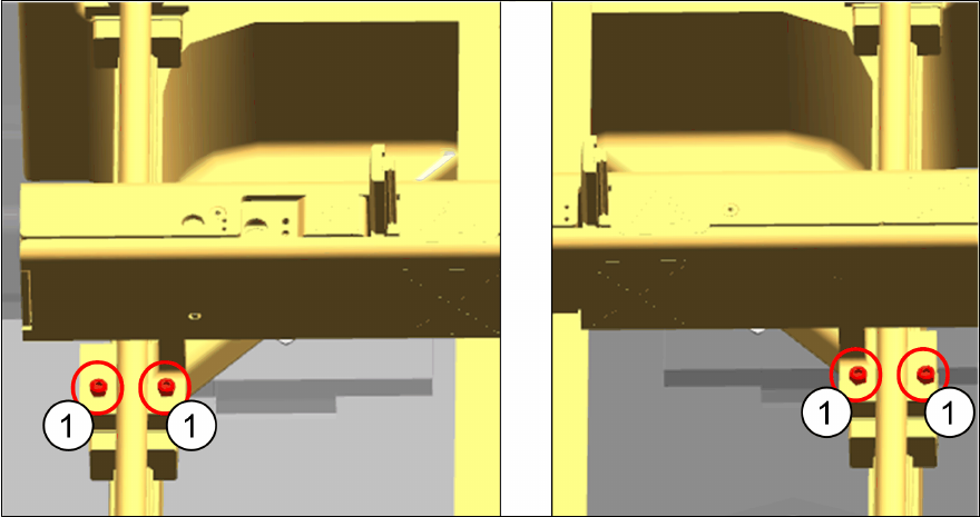
Fig.7: Stopper rail screws
► Remove the cable ties that fix the stopper rail cables.
► Remove the stopper rail screws (1).
2 Conversion
2.3 Steps and procedure
Assembly Instructions E by SIPLACE
Conveyor Conversion Kit 03/2017
18
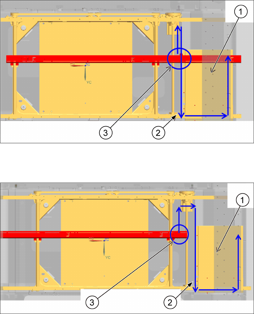
► Following the BOM shown in section 2.2 "BOM Identification" [}13] assemble the respective
stopper rail using the screw mentioned above.
► Route the cable according to the diagram shown below. Follow the original cable routing.
► Connect the cable connectors to the TSP by matching the “X” marking on the cable to the
marking on the TSP.
Fig.8: E-Series Stopper Assembly Right [03106875-xx]
1 TSP 2 Cable route
3 Cable exit point
Fig.9: E-Series Stopper Assembly Left [03106570-xx]
1 TSP 2 Cable route
3 Cable exit point
► Mount the TSP covers.