00198352-01_AI_Conveyor_Conversion_Kit_E-by-SIPLACE_EN - 第24页
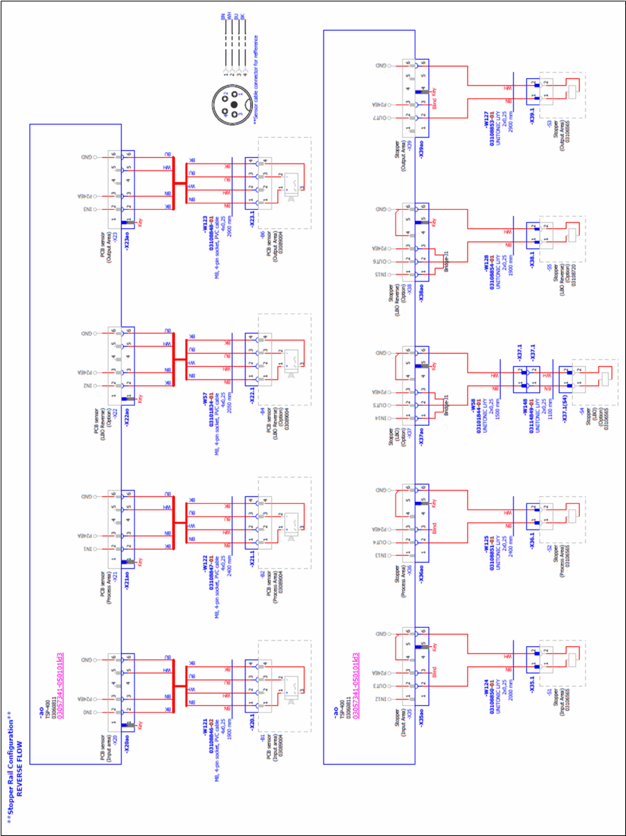
3 Cable harness for the LBO E 1030 and 1200 3.4 Reverse flow (Left Fix, Multi Line Connections) Assembly Instructions E by SIPLACE Conveyor Conversion Kit 03/2017 24
Assembly Instructions E by SIPLACE
Conveyor Conversion Kit 03/2017
3 Cable harness for the LBO E 1030 and 1200
3.4 Reverse flow (Left Fix, Multi Line Connections)
23
3.4 Reverse flow (Left Fix, Multi Line Connections)
Fig.13: Reverse flow (Left Fix, Multi Line Connections)
3 Cable harness for the LBO E 1030 and 1200
3.4 Reverse flow (Left Fix, Multi Line Connections)
Assembly Instructions E by SIPLACE
Conveyor Conversion Kit 03/2017
24
Assembly Instructions E by SIPLACE
Conveyor Conversion Kit 03/2017
4 Software Installation
4.1 SIRIO Station Software Re-Installation after Hardware Conversion
25
4 Software Installation
4.1 SIRIO Station Software Re-Installation after Hardware
Conversion
After the conveyor hardware kit conversion has been done. The SIRIO station must be re-installed
so that the correct configuration files are running on the machine.
► For Right fixed E-machine, select machine type E1R during SIRIO station software installa-
tion.
► For Left fixed E-machine, select machine type E1L during SIRIO station software installation.
Refer to SIRIO installation guideline for software installation.
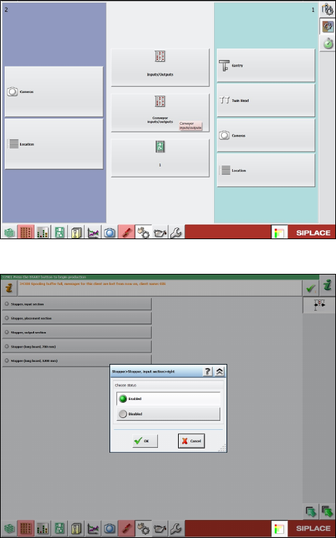
4.2 Stopper and Board sensor functional check
Manual functional check on the stopper and board sensor condition after software installation:
Fig.14: Conveyor inputs/outputs
► Go to Conveyor inputs/outputs function.
Fig.15: Example of a machine with both LBO 700 and 1200 mm
stopper installed
► Enable stopper function for all available stopper
selection.