00196056-0102 RI Shutterless 3x8 SL.pdf - 第4页
Inhaltsverzeichnis 4 Nachrüstanleitung / Retrofit In structions Feeder Module 3x8 mm S 0201/0402 to 5 Introduction. . . . . . . . . . . . . . . . . . . . . . . . . . . . . . . . . . . . . . . . . . . . . . . . . . . . . …
Inhaltsverzeichnis
Nachrüstanleitung / Retrofit Instructions Feeder Module 3x8 mm S 0201/0402 to Shutterless (3X8 mm SL)
3
Inhaltsverzeichnis
1 Einleitung . . . . . . . . . . . . . . . . . . . . . . . . . . . . . . . . . . . . . . . . . . . . . . . . . . . . . . . . . . . . 5
1.1 Lieferumfang ......................................................................................................................................... 5
1.2 Benötigte Hilfsmittel ............................................................................................................................. 6
1.3 Ersatzteile .............................................................................................................................................. 7
1.4 Sicherheitshinweise ............................................................................................................................. 7
1.5 Darstellungsmittel................................................................................................................................. 7
2 Software installieren . . . . . . . . . . . . . . . . . . . . . . . . . . . . . . . . . . . . . . . . . . . . . . . . . . . 9
2.1 Systemvoraussetzungen...................................................................................................................... 9
2.2 Installation starten ................................................................................................................................ 9
2.3 Installation durchführen..................................................................................................................... 10
2.4 Verbindung prüfen.............................................................................................................................. 12
2.5 COM-Port-Einstellung ändern............................................................................................................ 12
3 Gurtkanal austauschen . . . . . . . . . . . . . . . . . . . . . . . . . . . . . . . . . . . . . . . . . . . . . . . . 15
3.1 Gurtkanal demontieren....................................................................................................................... 15
3.1.1 Rechtes Seitenblech entfernen............................................................................................................. 15
3.1.2 Vordere Schutzplatte lösen................................................................................................................... 15
3.1.3 Gurtkanal entfernen .............................................................................................................................. 16
3.1.4 Klappen lösen ....................................................................................................................................... 17
3.2 Shutterless-Gurtkanal montieren ...................................................................................................... 18
3.2.1 Klappen am Shutterless-Gurtkanal befestigen ..................................................................................... 18
3.2.2 Shutterless-Gurtkanal befestigen.......................................................................................................... 19
3.2.3 Vordere Schutzplatte befestigen........................................................................................................... 21
3.2.4 Rechtes Seitenblech befestigen ........................................................................................................... 21
4 Feeder-ID auf dem EEPROM ändern . . . . . . . . . . . . . . . . . . . . . . . . . . . . . . . . . . . . . 23
4.1 Schnittstellenkästchen anschließen ................................................................................................. 23
4.2 Zuführmodul anschließen .................................................................................................................. 24
4.3 EEPROM programmieren ................................................................................................................... 24
4.4 Zuführmodul lösen ............................................................................................................................. 25
4.5 Etikett aufkleben / entfernen.............................................................................................................. 25
Inhaltsverzeichnis
4 Nachrüstanleitung / Retrofit Instructions Feeder Module 3x8 mm S 0201/0402 to
5 Introduction. . . . . . . . . . . . . . . . . . . . . . . . . . . . . . . . . . . . . . . . . . . . . . . . . . . . . . . . . .27
5.1 Scope of Delivery ................................................................................................................................ 27
5.2 Tools and Equipment.......................................................................................................................... 28
5.3 Spare Parts .......................................................................................................................................... 28
5.4 Safety Instructions.............................................................................................................................. 29
5.5 Display Features ................................................................................................................................. 29
6 Installing the Software . . . . . . . . . . . . . . . . . . . . . . . . . . . . . . . . . . . . . . . . . . . . . . . . .31
6.1 System Requirements ........................................................................................................................ 31
6.2 Starting the Installation ...................................................................................................................... 31
6.3 Performing the Installation................................................................................................................. 31
6.4 Checking the Connection................................................................................................................... 32
6.5 Changing the COM Port Setting ........................................................................................................ 33
7 Replacing the Tape Duct . . . . . . . . . . . . . . . . . . . . . . . . . . . . . . . . . . . . . . . . . . . . . . .35
7.1 Dismantling the Tape Duct................................................................................................................. 35
7.1.1 Removing the Right-Hand Side Plate ................................................................................................... 35
7.1.2 Removing the Front Protective Cover ................................................................................................... 35
7.1.3 Removing the Tape Duct ...................................................................................................................... 36
7.1.4 Loosening the Flaps.............................................................................................................................. 37
7.2 Fitting the Shutterless Tape Duct...................................................................................................... 38
7.2.1 Fixing the Flaps on the Shutterless Tape Duct ..................................................................................... 38
7.2.2 Fixing the Shutterless Tape Duct .......................................................................................................... 39
7.2.3 Fixing the Front Protective Cover.......................................................................................................... 41
7.2.4 Fixing the Right-Hand Side Plate .......................................................................................................... 41
8 Changing the Feeder ID on the EEPROM. . . . . . . . . . . . . . . . . . . . . . . . . . . . . . . . . .43
8.1 Connecting the Interface Unit ............................................................................................................ 43
8.2 Connecting the Feeder ....................................................................................................................... 44
8.3 Programming the EEPROM................................................................................................................ 44
8.4 Disconnecting the Feeder .................................................................................................................. 45
8.5 Attaching /Removing Labels.............................................................................................................. 45
Einleitung
Lieferumfang
Nachrüstanleitung / Retrofit Instructions Feeder Module 3x8 mm S 0201/0402 to Shutterless (3X8 mm SL)
5
1 Einleitung
Durch das Auswechseln eines herkömmlichen Gurtkanals gegen einen Shutterless-Gurtkanal können
Sie aus Ihren 3x8 mm S-Zuführmodulen in wenigen Arbeitsschritten einen 3x8 mm Shutterless Feeder
erzeugen.
Im Folgenden finden Sie eine Beschreibung der für diesen Umbau nötigen Arbeitsschritte.
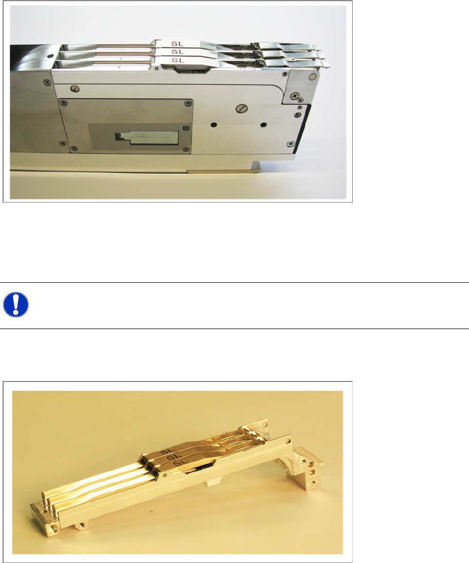
1.1 Lieferumfang
Den Nachrüstsatz zum Shutterless Feeder können Sie bestellen unter der Bezeichnung:
Nachrüstsatz Gurtfoerderer 3x8mm SL, Artikel-Nr. 03053307-01
In dem Nachrüstsatz sind enthalten:
1 komplett aufgebauter Gurtkanal SL Feeder
1 Etikett mit der Beschriftung 00141088-01, Artikel-Nr. 00329723-01
HINWEIS:
Beachten Sie, dass der Umbau nur von für 3x8 mm S-Zuführmodule geschultem Fachpersonal
durchgeführt werden sollte.