00196056-0102 RI Shutterless 3x8 SL.pdf - 第42页
Replacing the Tape Duct Fitting the Shutterless Tape Duct Fixing the Front Protective Cover 42 Nachrüstanleitung / Retrofit In structions Feeder Module 3x8 mm S 0201/0402 to 7.2.3 Fixing the Front Protective Cover 7.2.4 …
Replacing the Tape Duct
Fixing the Shutterless Tape Duct Fitting the Shutterless Tape Duct
Nachrüstanleitung / Retrofit Instructions Feeder Module 3x8 mm S 0201/0402 to Shutterless (3X8 mm SL)
41
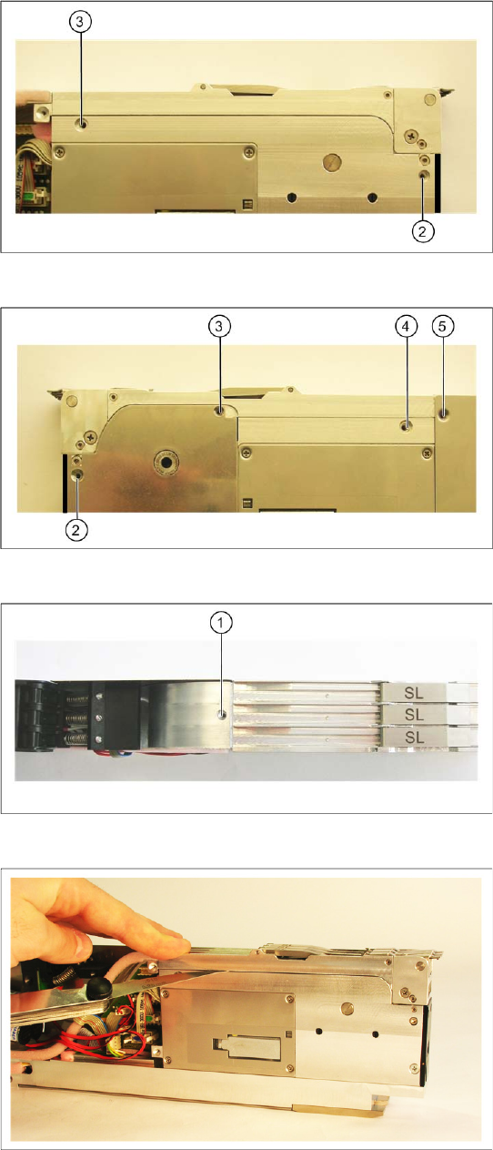
X Fix the shutterless tape duct onto the front of
the feeder, with the screws shown in the
diagram (2 and 3), on the right of the feeder.
X Fix the shutterless tape duct onto the front of
the feeder, with the screws shown in the
diagram (2-5), on the left of the feeder.
X Fix the shutterless tape duct to the top of the
feeder, with the screw (1).
Attention!
Tighten the screw carefully and not too tightly,
otherwise the aluminum thread could be
damaged.
X Use a feeler gauge (0.25 mm) to once again
check the tape duct distance, on the left and
right of the feeder. The tape duct should be
parallel to the drive housing.
If the distance is not correct, loosen the screw at
the top (1), those on the right (2 and 3) those on
the left (2-5) of the feeder and realign the tape
duct.
Replacing the Tape Duct
Fitting the Shutterless Tape Duct Fixing the Front Protective Cover
42 Nachrüstanleitung / Retrofit Instructions Feeder Module 3x8 mm S 0201/0402 to
7.2.3 Fixing the Front Protective Cover
7.2.4 Fixing the Right-Hand Side Plate
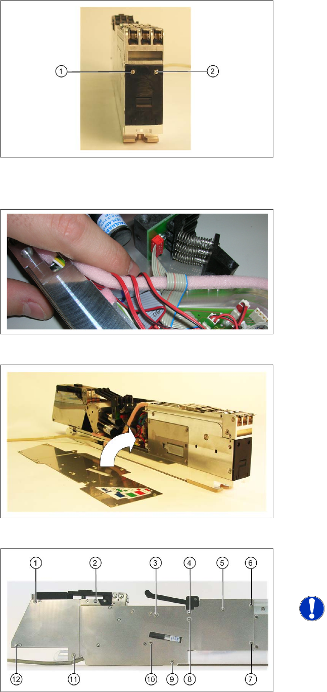
X Fix the protective cover with the two screws (1
and 2) to the front of the feeder.
X Make sure that the cables – as shown in the
diagram - are run next to one another,
otherwise the side plate will protrude too much
later on.
X Lift the right-hand side plate onto the right side
of the feeder.
X Fix the side plate onto the right-hand side of
the feeder, with the screws shown in the
diagram (1-12) .
NOTE:
Make sure that you use the correct
screws to fix the side plate (in their
original positions).
Changing the Feeder ID on the EEPROM
Connecting the Interface Unit
Nachrüstanleitung / Retrofit Instructions Feeder Module 3x8 mm S 0201/0402 to Shutterless (3X8 mm SL)
43
8 Changing the Feeder ID on the EEPROM
After conversion or reassembly, the feeder ID on the feeder EEPROM needs to be updated.
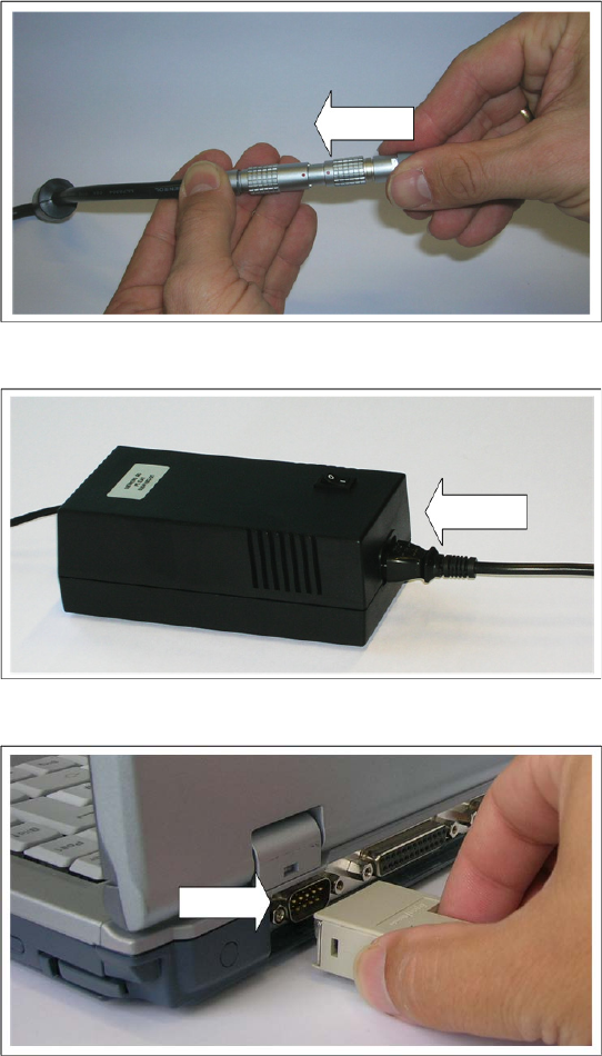
8.1 Connecting the Interface Unit
The interface unit ensures the power supply and the data exchange between the PC and the feeder
connected to the interface unit. The power supply and the data line are combined in one cable in the
interface unit and are then run to the feeder.
X Connect the power supply cable of the
interface unit with the corresponding cable
from the power pack. Make sure that the red
dot is at the top of both connectors.
X Connect the inlet connector to the power pack.
X Connect the mains connector to an earthed
shockproof socket.
X Connect the serial port of the interface unit to
the COM port of your PC.