00195963-03_MM SWS-EN.pdf - 第14页
Legend [1] Screw Remove t he screw t hat fixes the m agazine lift to the SWS. At locati ons 1 and 3 t hese sc rews are lo - cated on the right side , at loc ations 2 and 4 on the left side. Swivel th e magazine lift …
13
After Completing the Maintenance Work
Close all protective covers of the placement machine and all previously opened modules of
the SWS (See ”Opening and Closing the Interior of the SWS” on page - 14.).
Remove the devices against unauthorized reactivation.
Switch on the SWS and the placement machine.
Opening and Closing the Interior of the SWS
Opening and Closing the Protective Covers of the Placement Machine
Open the relevant protective cover of the placement machine, to make the interior of the SWS
accessible from above.
Carry out the necessary maintenance work and close the protective cover.
Swiveling out the Magazine Lift
For maintenance work on modules that cannot be accessed from above, it is necessary to make
the interior of the SWS accessible via the front.
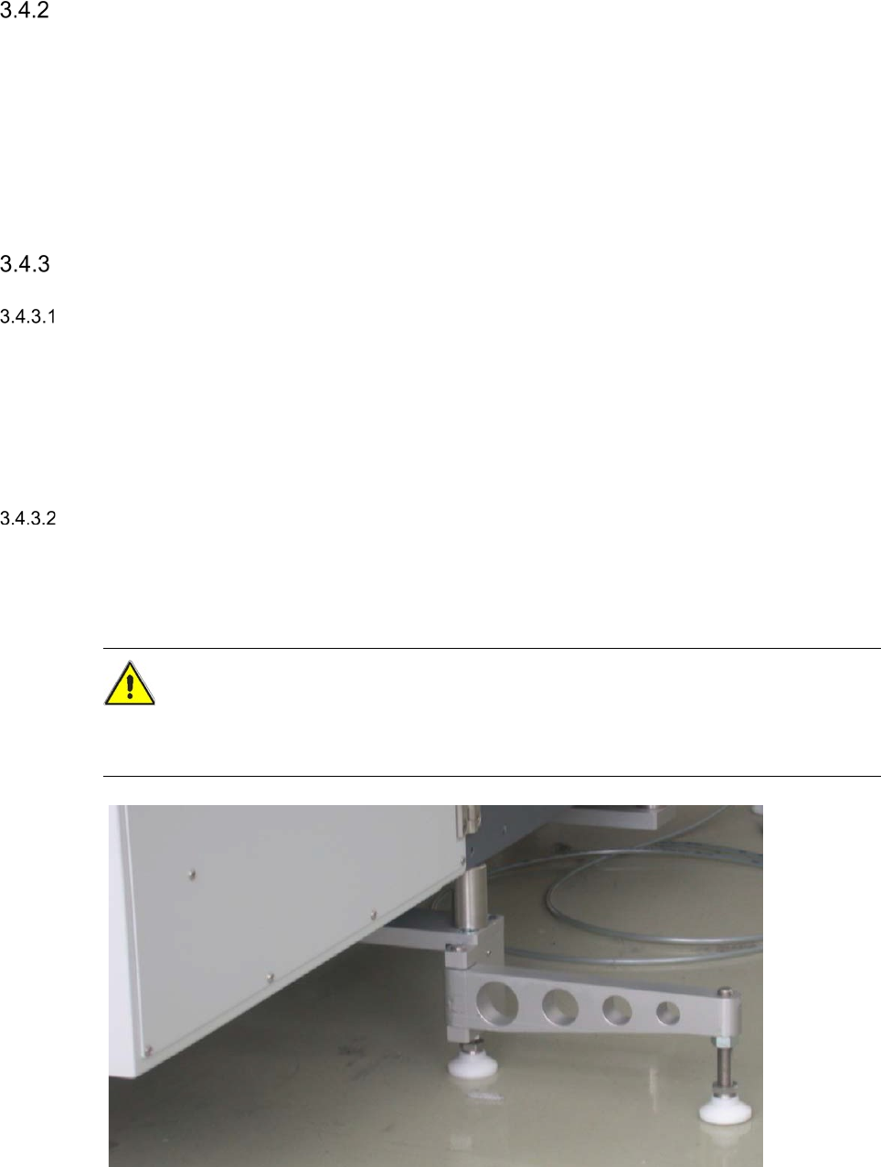
CAUTION
Make absolutely sure that the supporting foot of the SWS is swung out to the side, before you
swivel open the magazine lift. Otherwise you risk that the magazine lift may tilt.
Swing the support foot of the SWS out to the side.
Open the lower door of the magazine lift using the machine key.
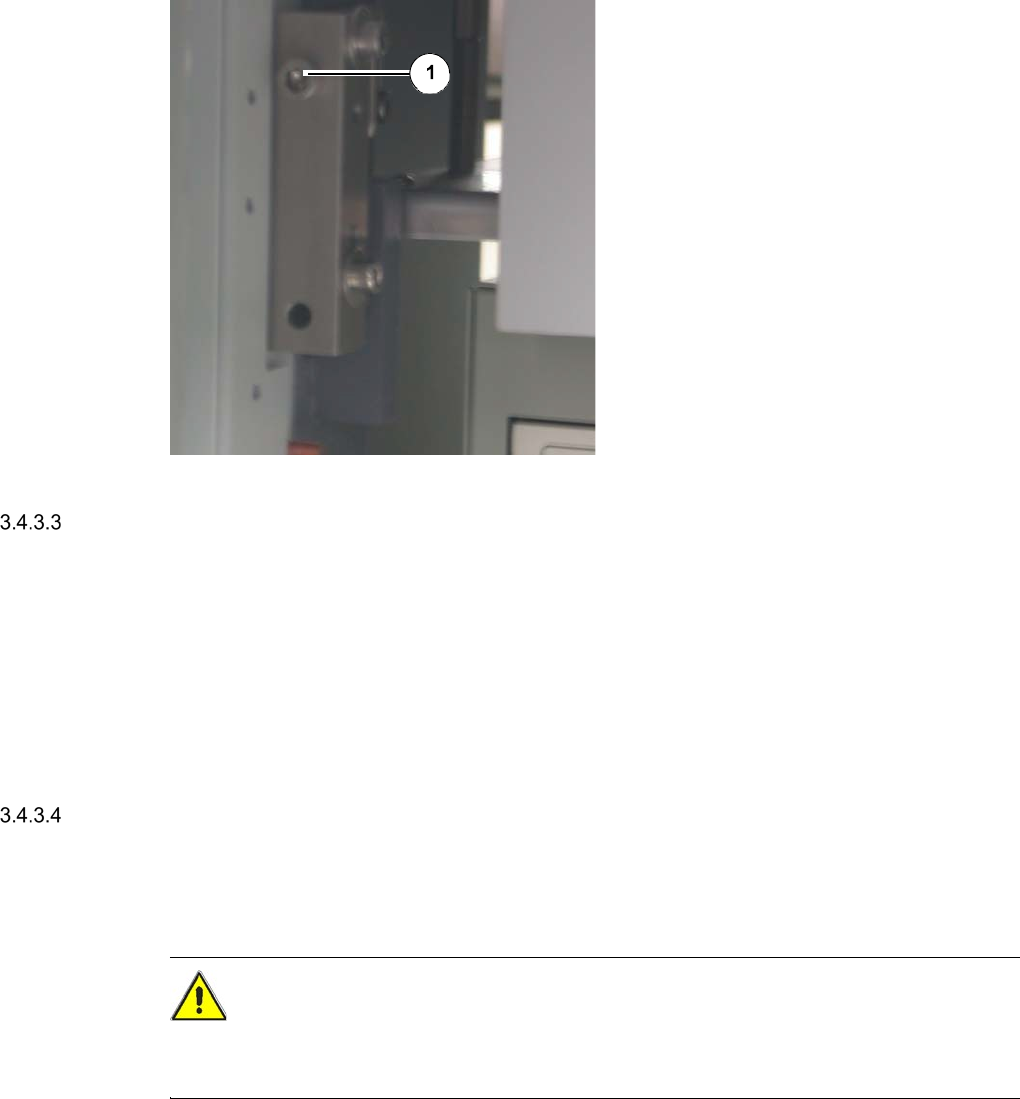
Legend
[1] Screw
Remove the screw that fixes the magazine
lift to the SWS.
At locations 1 and 3 these screws are lo-
cated on the right side, at locations 2 and 4
on the left side.
Swivel the magazine lift to the side.
The interior of the SWS is now accessible
via the front.
Carry out the necessary maintenance work
and close the magazine lift.
Closing the Magazine Lift
Swivel the magazine lift back to its initial position.
Fix the magazine lift to the SWS with the two previously removed screws.
Close the lower door of the magazine lift using the machine key.
Swing the support foot of the SWS back in, so that it stands parallel to the SWS (See ”Fig.
2.5 - 1” on page - 20.).
Pulling out the Supply Unit
For maintenance work on components that must be accessible from the front and the side, it is
additionally necessary to pull out the supply unit.
CAUTION
When pulling out or pushing in the supply unit, make absolutely sure, that the electrical cables
and pneumatic lines do not get caught or even pulled of.
Open the magazine lift (See ”Swiveling out the Magazine Lift” on page - 14.).
Remove the two screws at the supply unit.
Pull the supply unit out.
Carry out the necessary maintenance work and push the supply unit back in.
15
Pushing in the Supply Unit
CAUTION
When pulling out or pushing in the supply unit, make absolutely sure, that the electrical cables
and pneumatic lines do not get caught or even pulled of.
Push the supply unit into the SWS.
Fix the supply unit with the two previously removed screws.
Close the magazine lift (See ”Closing the Magazine Lift” on page - 15.).
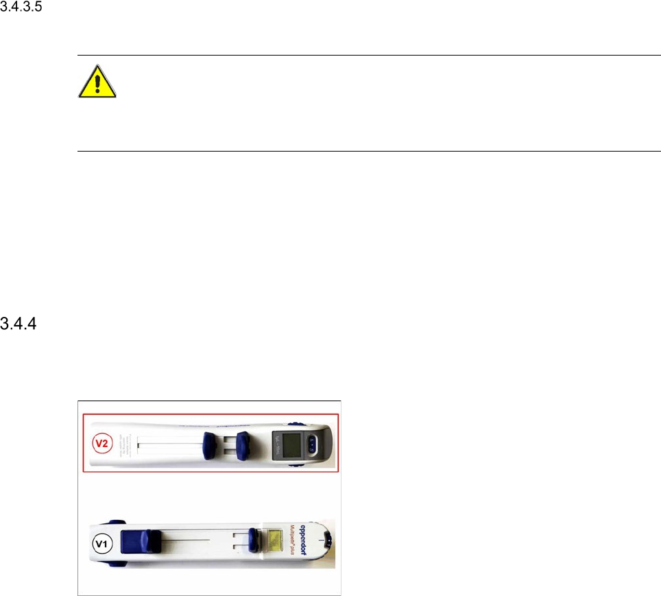
Using the Multipette
Use the Multipette V1 or V2for lubricating the linear guides of the flip chip unit and the die attach unit.
Both Multipettes have identical features, the handling for both versions is decribed in following
sub-chapters.
If you place a new order, you will receive the Version 2!