00198460-01_DC_SIPLACE_TX-EditionV2_DE+EN.pdf - 第11页
electric_schematic SIPLACE TX_V2 electric_schematic SIPLACE TX_V2 electric_schematic SIPLACE TX_V2 electric_schematic SIPLACE TX_V2 90012669-010501LE3 Replaced by Machine label Distributor Machine label Distributor Machi…
electric_schematic SIPLACE TX_V2
electric_schematic SIPLACE TX_V2
electric_schematic SIPLACE TX_V2
electric_schematic SIPLACE TX_V2
90012669-010501LE3
Replaced by
Machine label Power unit F&D
Machine label Power unit F&D
Machine label Power unit F&D
Machine label Power unit F&D
Replaced by
Weitergabe sowie Vervielfältigung dieser Unterlage, Verwertung und
Mitteilung des Inhalts nicht gestattet, soweit nicht ausdrücklich zugestanden.
Proprietary Data, company confidential.
All rights reserved
Copying of this document, giving it to others and the use or
communication of the contents thereof, are forbidden without express authority.
Doc. No.
Privileged business information.
Do not release
Offenders are liable to payment of damages. All rights are reserved in the
event of the grant or the registration of a utility model or design.
Zuwiederhandlungen verpflichten zu Schadenersatz. Alle Rechte vorbehalten,
insbesondere für den Fall der Patenterteilung oder GM-Eintragung vorbehalten.
Page:
Function: Overview Graphics
==OVGR=TX+ME/5
drawing number:
03146155-010701LE3
overview_graphics
o
verview_graphics
overview_graphics
overview_graphics
GmbH & Co KG
ASM
Assembly Systems
Copyright reserved
Ed.
Original
Pingist
Date
Date
Modification
Appr
24.01.2018
Name
Size DIN A2
Sheet
5
/
5
F1
F1
F1
F1 F12
F12
F12
F12 F21
F21
F21
F21 F11
F11
F11
F11 F16
F16
F16
F16 F15
F15
F15
F15 F14
F14
F14
F14 F6
F6
F6
F6
F3
F3
F3
F3 F4
F4
F4
F4 F5
F5
F5
F5 F7
F7
F7
F7
X25
X25
X25
X25
X26
X26
X26
X26
X5
X5
X5
X5
X1
X1
X1
X1
X16
X16
X16
X16
X9
X9
X9
X9
X10
X10
X10
X10
X14
X14
X14
X14
X15
X15
X15
X15
X13
X13
X13
X13
X8
X8
X8
X8
X17
X17
X17
X17
X24B
X24B
X24B
X24B
X12
X12
X12
X12 X11
X11
X11
X11
XB8B
XB8B
XB8B
XB8B XB8A
XB8A
XB8A
XB8A
F19
F19
F19
F19
F20
F20
F20
F20
DC/DC1
DC/DC1
DC/DC1
DC/DC1
(BUFF1)
(BUFF1)
(BUFF1)
(BUFF1)
C109
C109
C109
C109C110
C110
C110
C110
C107
C107
C107
C107
C106
C106
C106
C106
C105
C105
C105
C105
C104
C104
C104
C104 C103
C103
C103
C103 C102
C102
C102
C102 C101
C101
C101
C101
C108
C108
C108
C108
C2
C2
C2
C2
C26
C26
C26
C26
Diagnostic unit
Diagnostic unit
Diagnostic unit
Diagnostic unit
X2
X2
X2
X2
DC/DC2
DC/DC2
DC/DC2
DC/DC2
(BUFF2)
(BUFF2)
(BUFF2)
(BUFF2)
DC/DC3
DC/DC3
DC/DC3
DC/DC3
(MGCU)
(MGCU)
(MGCU)
(MGCU)
X24A
X24A
X24A
X24A
F1
F3
F4
F5
F6
F7
F10
F11
F12
F13
F14
F15
F16
F19
F20
F21
42V
24V
24V
24V
42V
24V
24V
24V
24V
24V
42/24V
42/24V
42V
160V
160V
42V
6,3 A T
6,3 A T
4 A T
6,3 A T
6,3 A T
6,3 A T
POLYFUSE
6,3 A T
6,3 A T
3 A SMD
6,3 A T
6,3 A T
10 A T
6,3 A T
6,3 A T
6,3 A T
Shuttle 42V
Shuttle 24V & Option
Distributor
Monitor 1&2 / CIN
MGCU supply 42 V
Conveyor control
Internal
CSB Signal
CSB supply 24V-S
Diagnostic supply
Gantry/Head 1
Gantry/Head 2
Conveyor drives
Gantry 1
Gantry 2
(Vision) not used
F31
F32
F33
27,5V
27,5V
27,5V
16 A C
16 A C
10 A C
FCU 1 (27V_FCU1)
FCU 2 (27V_FCU2)
Station PC (27V_PC)
Risk of fire and electric shock!
Risk of fire and electric shock!
Risk of fire and electric shock!
Risk of fire and electric shock!
Replace fuses by specified service parts only!
Replace fuses by specified service parts only!
Replace fuses by specified service parts only!
Replace fuses by specified service parts only!
!
safety
safety
safety
safety
controlled
controlled
controlled
controlled
voltage
voltage
voltage
voltage
S
S
S
S
Indicator near fuse will show that
Indicator near fuse will show that
Indicator near fuse will show that
Indicator near fuse will show that
fuse is blown or
fuse is blown or
fuse is blown or
fuse is blown or
safety controlled voltage
safety controlled voltage
safety controlled voltage
safety controlled voltage
is off
is off
is off
is off
High Voltage
High Voltage
High Voltage
High Voltage
behind cover
behind cover
behind cover
behind cover
S
S
S
S
S
S
S
S
S
S
S
S
S
S
S
S
Line Breakers (at FCU supply unit)
Line Breakers (at FCU supply unit)
Line Breakers (at FCU supply unit)
Line Breakers (at FCU supply unit)
Status
Status
Status
Status
POWER ENABLE
POWER ENABLE
POWER ENABLE
POWER ENABLE
POWER OK
POWER OK
POWER OK
POWER OK
K1 OK
K1 OK
K1 OK
K1 OK
K2 OK
K2 OK
K2 OK
K2 OK
POWER FAIL
POWER F
AIL
POWER FAIL
POWER FAIL
POWER FAIL PS2
POWER F
AIL PS2
POWER FAIL PS2
POWER FAIL PS2
27V PC
27V PC
27V PC
27V PC
+3V3
+3V3
+3V3
+3V3
+5V0 EXT
+5V0 EXT
+5V0 EXT
+5V0 EXT
DC 24V_S_CO
DC 24V_S_CO
DC 24V_S_CO
DC 24V_S_CO
P24V_MGCU
P24V_MGCU
P24V_MGCU
P24V_MGCU
P24V_BUFF1
P24V_BUFF1
P24V_BUFF1
P24V_BUFF1
P24V_BUFF2
P24V_BUFF2
P24V_BUFF2
P24V_BUFF2
27V_FCU1
27V_FCU1
27V_FCU1
27V_FCU1
27V_FCU2
27V_FCU2
27V_FCU2
27V_FCU2
V2
V2
V2
V2
PE
PE
PE
PEGND
GND
GND
GND
S
S
S
S
03152559-030101GX4
electric_schematic SIPLACE TX_V2
electric_schematic SIPLACE TX_V2
electric_schematic SIPLACE TX_V2
electric_schematic SIPLACE TX_V2
90012669-010501LE3
Replaced by
Machine label Distributor
Machine label Distributor
Machine label Distributor
Machine label Distributor
Replaced by
Weitergabe sowie Vervielfältigung dieser Unterlage, Verwertung und
Mitteilung des Inhalts nicht gestattet, soweit nicht ausdrücklich zugestanden.
Proprietary Data, company confidential.
All rights reserved
Copying of this document, giving it to others and the use or
communication of the contents thereof, are forbidden without express authority.
Doc. No.
Privileged business information.
Do not release
Offenders are liable to payment of damages. All rights are reserved in the
event of the grant or the registration of a utility model or design.
Zuwiederhandlungen verpflichten zu Schadenersatz. Alle Rechte vorbehalten,
insbesondere für den Fall der Patenterteilung oder GM-Eintragung vorbehalten.
Page:
Function: Overview Graphics
==OVGR=TX+ME/6
drawing number:
03156683-010101LE3
overview_graphics
o
verview_graphics
overview_graphics
overview_graphics
GmbH & Co KG
ASM
Assembly Systems
Copyright reserved
Ed.
Original
Pingist
Date
Date
Modification
Appr
24.01.2018
Name
Size DIN A2
Sheet
6
/
5
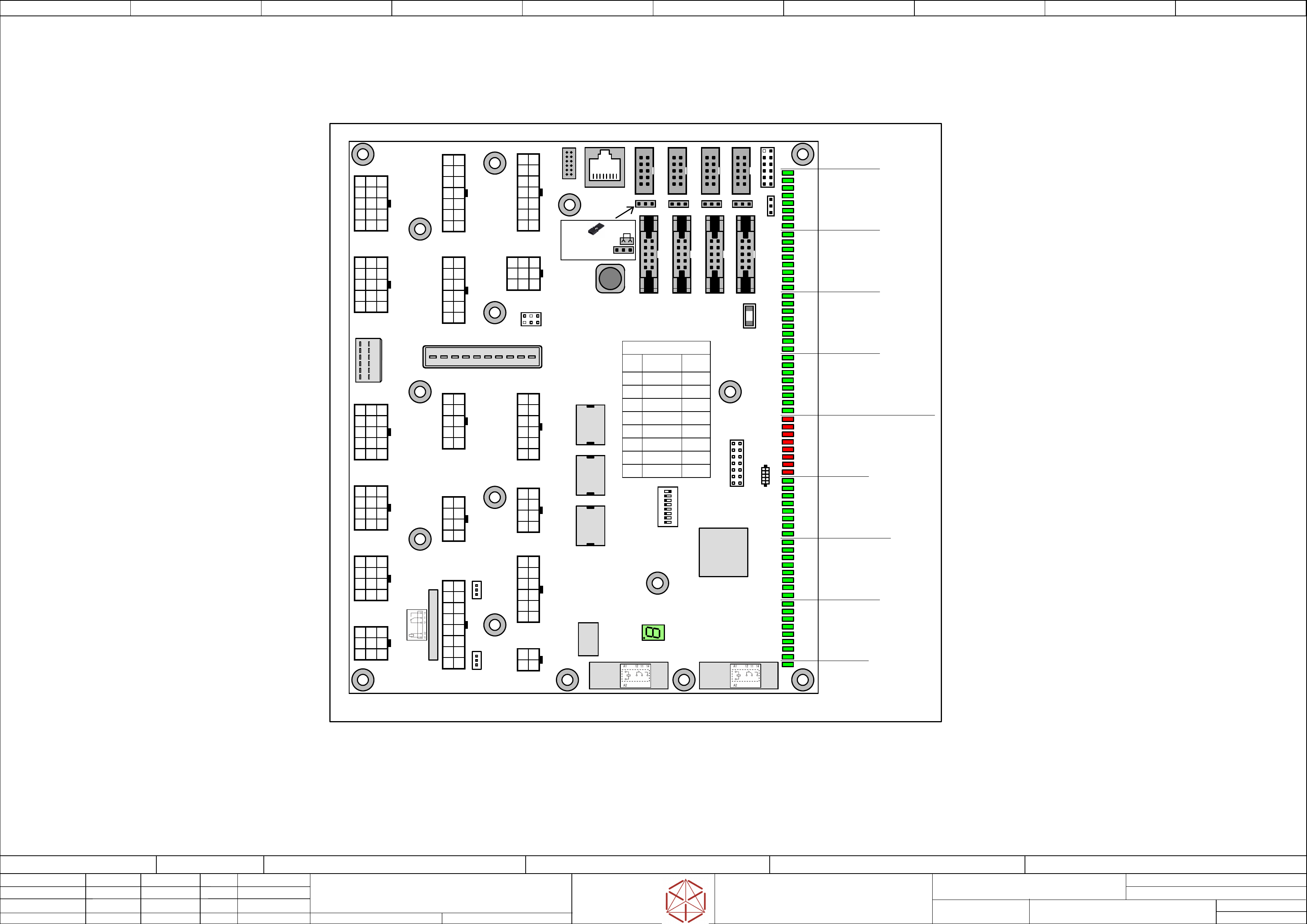
SW1
SW1
SW1
SW1
CAN_1 Service
CAN_1 Service
CAN_1 Service
CAN_1 Service
Communication
to FUSE-
Detection
Option-Switches
RS485
for PSU
-X22
-
X22
-X22
-X22
Safety-Loop &
Signals from
Power supply
SMPS
Power 24V DC
from Fuse and
distribution board
-X28
-
X28
-X28
-X28
.DI
.DI
.DI
.DI
Distributor
Distributor
Distributor
Distributor
TX_V2
TX_V2
TX_V2
TX_V2
03147585-xx
03147585-
xx
03147585-xx
03147585-xx
COT-insert 1 / Fixed table 1
Signaling & Safety
Relays
K2
K2
K2
K2
K4
K4
K4
K4
Relays
O F F
O F F
O F F
O F F
2
2
2
23
3
3
34
4
4
45
5
5
56
6
6
67
7
7
78
8
8
8 1
1
1
1
Option-Switches SW1
Switch
Switch Coding position
SW1.1 TX-Series ON
SW1.2 Reserved OFF
SW1.3 Reserved OFF
SW1.4 Reserved OFF
SW1.5 Reserved OFF
SW1.6 Normal mode OFF
SW1.7 Normal mode OFF
SW1.8 Normal mode OFF
A1
A1
A1
A1
-X21
-
X21
-X21
-X21
1
1
1
1
-X6
-
X6
-X6
-X6
X1_1
X1_1
X1_1
X1_1
X2_1
X2_1
X2_1
X2_1
-X13
-
X13
-X13
-X13
Control elements 2 back
Start / Stop 2
1
1
1
1
-X24
-
X24
-X24
-X24
Control elements 1 front
Start / Stop 1
1
1
1
1
-X23
-
X23
-X23
-X23
-X25
-
X25
-X25
-X25
Service- and
Test-Interface
1
1
1
1
-X30
-
X30
-X30
-X30
Control Vaccum_Pump
Control Interior light off/on
Reserve digital input/output
1
1
1
1
-X31
-X31
-X31
-X31
Pneumatic_Main_System
1
1
1
1
-X32
-
X32
-X32
-X32
Fault indicator lamp
1
1
1
1
1
1
1
1 1
1
1
1 1
1
1
1 1
1
1
1
1
1
1
1
X1
X1
X1
X1
CAN1
CAN1
CAN1
CAN1
X2
X2
X2
X2
CAN2
CAN2
CAN2
CAN2
X3
X3
X3
X3
CAN3
CAN3
CAN3
CAN3
CAN4
CAN4
CAN4
CAN4
LED1
LED1
LED1
LED1
Status
Status
Status
Status
Frequeny
converter
1
1
1
1
-X19
-
X19
-X19
-X19
● MP10 +24V(F3)
● MP 9 +24V0
● MP12 LGND
● MP13 24V_S
● MP11
+24V(F6)
-X29
-X29
-X29
-X29
COT-insert 2 / Fixed table 2
Signaling & Safety
1
1
1
1
1
1
1
1
-X27
-
X27
-X27
-X27
Security Loop
Control elements Hood 2
1
1
1
1
-X50
-
X50
-X50
-X50
FCU-Connection
Assembly
1
1
1
1
-X33
-
X33
-X33
-X33
Reserve-I/O & Optional
Laterial channel blower
1
1
1
1
-X35
-
X35
-X35
-X35
Fan Control & Monitoring_2
Fan_5 ... Fan_8
1
1
1
1
-X37
-X37
-X37
-X37
Reserve-I/O &
K3-Connection
1
1
1
1
-X40
-
X40
-X40
-X40
Jumper
1
1
1
1
1
1
1
1
-X41
-
X41
-X41
-X41
Jumper
-X26
-
X26
-X26
-X26
Security Loop
Control elements Hood 1
1
1
1
1
-X34
-X34
-X34
-X34
Fan Control & Monitoring_1
Fan_1 ... Fan_4
1
1
1
1
-X36
-
X36
-X36
-X36
Security Loop extern &
Flap Ex.Conveyor
1
1
1
1
-X38
-
X38
-X38
-X38
Power 24V DC _ PC2
1
1
1
1
Coil: 24VDC,
Rated current: 6A
Relays
R
elays
Relays
Relays
K3
K3
K3
K3
CAN_2 Service
CAN_2 Service
CAN_2 Service
CAN_2 Service
CAN_3 Service
CAN_3 S
ervice
CAN_3 Service
CAN_3 Service
X3_1
X3_1
X3_1
X3_1
CAN_4 Service
CAN_4 Service
CAN_4 Service
CAN_4 Service
X4_1
X4_1
X4_1
X4_1
CAN_5
CAN_5
CAN_5
CAN_5
1
1
1
11
1
1
11
1
1
1 1
1
1
1
1
1
1
1
-X7
-X7
-X7
-X7 -X8
-X8
-X8
-X8 -X9
-X9
-X9
-X9
-X5
-
X5
-X5
-X5
ON
ON
ON
ON
ON
ON
ON
ON
1
1
1
1
-X10
-
X10
-X10
-X10
Analog + Program
1
1
1
1
-X98
-
X98
-X98
-X98
Debug
K1
K1
K1
K1
Relays
Relays
Relays
Relays
DI_0 SAFETY_LOOP_OK
DI_1 ----
DI_2 EMG_STOP_2
DI_3 ----
DI_4 PRESSENS_PV1
DI_5 PRESSENS_MAINVALVE (not used)
DI_6 Identify_Vacuum pump
DI_7 ----
DI_8 START_BUTTON_1
DI_9 STOP_BUTTON_1
DI_10 24V_S (SSK)
DI_11 START_BUTTON_2
DI_12 STOP_BUTTON_2
DI_13 PWR_ENABLED
DI_14 EMG_STOP1
DI_15 EMG_STOP_EXT
DI_16 BUTTON_COTI_2
DI_17 HOOD_2
DI_18 COMP_TABLE_2
DI_19 HOOD2_LOCK_ON
DI_20 ----
DI_21 ----
DI_22 ----
DI_23 ----
DI_24 BUTTON_COTI_1
DI_25 HOOD_1
DI_26 COMP_TABLE_1
DI_27 HOOD1_LOCK_ON
DI_28 ----
DI_29 Flap_ExCo (Opt. ext._Conveyor)
DI_30 Flap_Lock_on ExCo (Opt. ext._Conveyor)
DI_31 Res. (Opt. ID_ext._Conveyor)
DI_32 FAN_1
DI_33 FAN_2
DI_34 FAN_3
DI_35 FAN_4
DI_36 FAN_5
DI_37 FAN_6
DI_38 FAN_7
DI_39 FAN_8
DO_0 ----
DO_1 CONTROL_ON
DO_2 ----
DO_3 PRESSURE_PV1
DO_4 HOOD_LOCK2
DO_5 HOOD_LOCK1
DO_6 Res. (Vac_Pump_ON)
DO_7 INTERIOR_LIGHT
DO_8 ----
DO_9 BUZZER
DO_10 INDICATOR_1_RD
DO_11 INDICATOR_2_RD
DO_12 INDICATOR_1_GN
DO_13 INDICATOR_1_YE
DO_14 INDICATOR_2_YE
DO_15 INDICATOR_2_GN
DO_16 SERVICE
DO_17 SERVICE
DO_18 SERVICE
DO_19 ----
DO_20 FAN-CONTROL
DO_21 ----
DO_22 ----
DO_23 ----
RESET
U40
U40
U40
U40
SAF-XE167F-
S
AF-XE167F-
SAF-XE167F-
SAF-XE167F-
96F66LAC
96F66L
AC
96F66LAC
96F66LAC
BTS4880R
BTS4880R
BTS4880R
BTS4880RBTS4880R
BTS4880R
BTS4880R
BTS4880RBTS4880R
BTS4880R
BTS4880R
BTS4880R
U25
U25
U25
U25
U11
U11
U11
U11
U13
U13
U13
U13
ON
ON
ON
ON ON
ON
ON
ON ON
ON
ON
ON
X4
X4
X4
X4
-X11
-X11
-X11
-X11
1
1
1
1
F1
F1
F1
F1
-X14
-X14
-X14
-X14
8
8
8
8
1
1
1
1
1
1
1
11
1
1
1 1
1
1
1
L3
L3
L3
L3
L3
L3
L3
L3
1
1
1
1
ON
ON
ON
ON
Jumper position
CAN-Bus Termination
for X5, X6, X7, X8, X9
electric_schematic SIPLACE TX_V2
electric_schematic SIPLACE TX_V2
electric_schematic SIPLACE TX_V2
electric_schematic SIPLACE TX_V2
90012669-010501LE3
Replaced by
Interface Panel to Machine Cable Harness
Interface Panel to Machine Cable Harness
Interface Panel to Machine Cable Harness
Interface Panel to Machine Cable Harness
Replaced by
Weitergabe sowie Vervielfältigung dieser Unterlage, Verwertung und
Mitteilung des Inhalts nicht gestattet, soweit nicht ausdrücklich zugestanden.
Proprietary Data, company confidential.
All rights reserved
Copying of this document, giving it to others and the use or
communication of the contents thereof, are forbidden without express authority.
Doc. No.
Privileged business information.
Do not release
Offenders are liable to payment of damages. All rights are reserved in the
event of the grant or the registration of a utility model or design.
Zuwiederhandlungen verpflichten zu Schadenersatz. Alle Rechte vorbehalten,
insbesondere für den Fall der Patenterteilung oder GM-Eintragung vorbehalten.
Page:
Function: Overview Graphics
==OVGR=TX+ME/7
drawing number:
03133452-010501LE3
overview_graphics
o
verview_graphics
overview_graphics
overview_graphics
GmbH & Co KG
ASM
Assembly Systems
Copyright reserved
Ed.
Original
Pingist
Date
Date
Modification
Appr
04.04.2018
Name
Size DIN A2
Sheet
7
/
5
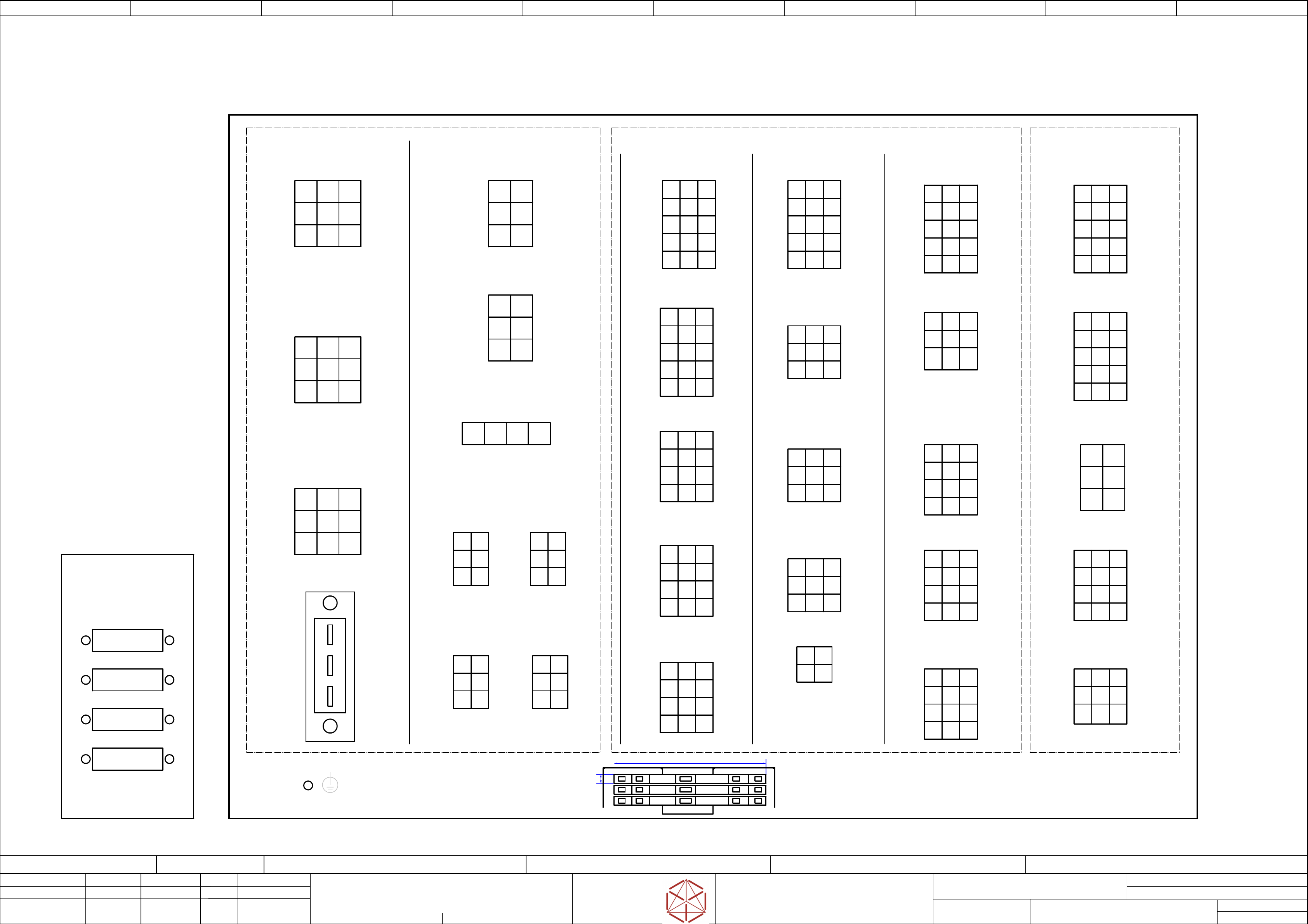
-X102
-X102
-X102
-X102
AC 400V Power_supply
AC 400V P
ower_supply
AC 400V Power_supply
AC 400V Power_supply
-- FDC --
-- FDC --
-- FDC --
-- FDC -- -- DIC --
-- DIC --
-- DIC --
-- DIC --
Fuse & Distribution Connector panel
Fuse & Distribution Connector panel
Fuse & Distribution Connector panel
Fuse & Distribution Connector panel
Signal Distributor Connector panel
Signal Distributor Connector panel
Signal Distributor Connector panel
Signal Distributor Connector panel
Layout Connector Panel Power Unit
Layout Connector Panel Power Unit
Layout Connector Panel Power Unit
Layout Connector Panel Power Unit
Mini-Mate.-N-Look 6pol
-X9
-
X9
-X9
-X9
DC 24V
DC 24V
DC 24V
DC 24V
PC screens
PC scr
eens
PC screens
PC screens
Mini-Mate.-N-Look 6pol
-X8B
-
X8B
-X8B
-X8B
Trailing interface 2
T
railing interface 2
Trailing interface 2
Trailing interface 2
& 160V
& 160V
& 160V
& 160V
Mate.-N-Look 6pol
-X12
-
X12
-X12
-X12
Trailing
T
railing
Trailing
Trailing
interface 2
interf
ace 2
interface 2
interface 2
Mini-Mate.-N-Look 6pol
Mini-Mate.-N-Look 6pol
-X8
-X8
-X8
-X8
Trailing
T
railing
Trailing
Trailing
interface 2
interf
ace 2
interface 2
interface 2
-X15
-
X15
-X15
-X15
Stuttle
Stut
tle
Stuttle
Stuttle
Mate.-N-Look 9pol
(Option)
-- CAN --
-- CAN --
-- CAN --
-- CAN --
-X16
-
X16
-X16
-X16
TCU
T
CU
TCU
TCU
Mate.-N-Look 9pol
(Option)
-X14
-X14
-X14
-X14
Conveyor
Con
veyor
Conveyor
Conveyor
Mate.-N-Look 9pol
-X11
-X11
-X11
-X11
Trailing
T
railing
Trailing
Trailing
interface 1
interf
ace 1
interface 1
interface 1
-X23
-
X23
-X23
-X23
Control elements 1
Contr
ol elements 1
Control elements 1
Control elements 1
Mini-Mate.-N-Look 15pol
-X27
-
X27
-X27
-X27
Control elements Hood 2
Contr
ol elements Hood 2
Control elements Hood 2
Control elements Hood 2
Mini-Mate.-N-Look 12pol
-X30
-
X30
-X30
-X30
Control Vaccum_Pump
Contr
ol Vaccum_Pump
Control Vaccum_Pump
Control Vaccum_Pump
Control Interior light
Contr
ol Interior light
Control Interior light
Control Interior light
Mini-Mate.-N-Look 12pol
Mini-Mate.-N-Look 15pol
-X24
-X24
-X24
-X24
Control elements 2
Contr
ol elements 2
Control elements 2
Control elements 2
-X26
-
X26
-X26
-X26
Control elements Hood 1
Contr
ol elements Hood 1
Control elements Hood 1
Control elements Hood 1
Mini-Mate.-N-Look 12pol
-X29
-
X29
-X29
-X29
COT-insert 2
CO
T-insert 2
COT-insert 2
COT-insert 2
Signaling & Safety
Signal
ing & Safety
Signaling & Safety
Signaling & Safety
Mini-Mate.-N-Look 15pol
-X32
-
X32
-X32
-X32
Fault indicator lamp
F
ault indicator lamp
Fault indicator lamp
Fault indicator lamp
Mini-Mate.-N-Look 9pol
-X35
-
X35
-X35
-X35
Fan control &
F
an control &
Fan control &
Fan control &
monitoring 2
moni
toring 2
monitoring 2
monitoring 2
Mini-Mate.-N-Look 9pol
-X19
-
X19
-X19
-X19
RS485 FU
RS485 FU
RS485 FU
RS485 FU
Mini-Mate.-N-Look 4pol
-X33
-
X33
-X33
-X33
Fault indicator lamp
F
ault indicator lamp
Fault indicator lamp
Fault indicator lamp
Mini-Mate.-N-Look 12pol
-X34
-
X34
-X34
-X34
Fan control &
F
an control &
Fan control &
Fan control &
monitoring 1
moni
toring 1
monitoring 1
monitoring 1
Mini-Mate.-N-Look 9pol
-X31
-
X31
-X31
-X31
Pneumatic_
Pneumatic_
Pneumatic_
Pneumatic_
Main_System
Main_S
ystem
Main_System
Main_System
Mini-Mate.-N-Look 12pol
-X28
-
X28
-X28
-X28
COT-insert 1
CO
T-insert 1
COT-insert 1
COT-insert 1
Signaling & Safety
Signal
ing & Safety
Signaling & Safety
Signaling & Safety
Mini-Mate.-N-Look 15pol
-X201
-
X201
-X201
-X201
Spare 1
Spar
e 1
Spare 1
Spare 1
Mini-Mate.-N-Look 15pol
-X202
-
X202
-X202
-X202
Spare 2
Spar
e 2
Spare 2
Spare 2
Mini-Mate.-N-Look 15pol
-X203
-X203
-X203
-X203
Spare 3
Spar
e 3
Spare 3
Spare 3
Mate.-N-Look 6pol
-X204
-
X204
-X204
-X204
Spare 4
Spar
e 4
Spare 4
Spare 4
Mini-Mate.-N-Look 12polMini-Mate.-N-Look 9 pol
-X205
-
X205
-X205
-X205
Spare 5
Spar
e 5
Spare 5
Spare 5
-- RES --
-- RES --
-- RES --
-- RES --
-X50
-
X50
-X50
-X50
COTi Supply
CO
Ti Supply
COTi Supply
COTi Supply
Mini-Mate.-N-Look pol
Spare Connectors panel
Spar
e Connectors panel
Spare Connectors panel
Spare Connectors panel
CAN Connector panel
CAN Connector panel
CAN Connector panel
CAN Connector panel
69 mm
4 mm
PE terminals
PE terminals
PE terminals
PE terminals
-PE
-PE
-PE
-PE
-X8A
-
X8A
-X8A
-X8A
Trailing interface 1
T
railing interface 1
Trailing interface 1
Trailing interface 1
& 160V
& 160V
& 160V
& 160V
Mate.-N-Look 6pol
Mate-N-Look 4pol
-X5
-X5
-X5
-X5
FCU voltage
FCU v
oltage
FCU voltage
FCU voltage
monitor
moni
tor
monitor
monitor
CAN1
CAN1
CAN1
CAN1
4x
Stiftleiste IDC 10-pin
mit Montageflansch
CAN2
CAN2
CAN2
CAN2
CAN3
CAN3
CAN3
CAN3
CAN4
CAN4
CAN4
CAN4
-X36
-
X36
-X36
-X36
Safety Loop Flap
Saf
ety Loop Flap
Safety Loop Flap
Safety Loop Flap
Ex.Conveyor
Ex.Con
veyor
Ex.Conveyor
Ex.Conveyor
Mini-Mate.-N-Look 12pol