00198460-01_DC_SIPLACE_TX-EditionV2_DE+EN.pdf - 第122页
electric_schematic SIPLACE TX_V2 electric_schematic SIPLACE TX_V2 electric_schematic SIPLACE TX_V2 electric_schematic SIPLACE TX_V2 90012669-010501LE3 Replaced by Safety -Loop overview Safety -Loop overview Safety -Loop …
electric_schematic SIPLACE TX_V2
electric_schematic SIPLACE TX_V2
electric_schematic SIPLACE TX_V2
electric_schematic SIPLACE TX_V2
90012669-010501LE3
Replaced by
Safety-Loop overview
Safety-Loop overview
Safety-Loop overview
Safety-Loop overview
contactor based safety breaker: logic
contactor based saf
ety breaker: logic
contactor based safety breaker: logic
contactor based safety breaker: logic
Replaced by
Weitergabe sowie Vervielfältigung dieser Unterlage, Verwertung und
Mitteilung des Inhalts nicht gestattet, soweit nicht ausdrücklich zugestanden.
Proprietary Data, company confidential.
All rights reserved
Copying of this document, giving it to others and the use or
communication of the contents thereof, are forbidden without express authority.
Doc. No.
0 1 2 3 4 5 6 7 8 9
Privileged business information.
Do not release
Offenders are liable to payment of damages. All rights are reserved in the
event of the grant or the registration of a utility model or design.
Zuwiederhandlungen verpflichten zu Schadenersatz. Alle Rechte vorbehalten,
insbesondere für den Fall der Patenterteilung oder GM-Eintragung vorbehalten.
Page:
Function: Emergency
==EMG=TX_EMG+CSB/116
drawing number:
90012669- EMG
Emergency Loop Documentation
Emer
gency Loop Documentation
Emergency Loop Documentation
Emergency Loop Documentation
GmbH & Co KG
ASM
Assembly Systems
Copyright reserved
Ed.
Original
Pingist
Date
Date
Modification
Appr
07.02.2018
Name
Size DIN A2
Sheet
116
/
1
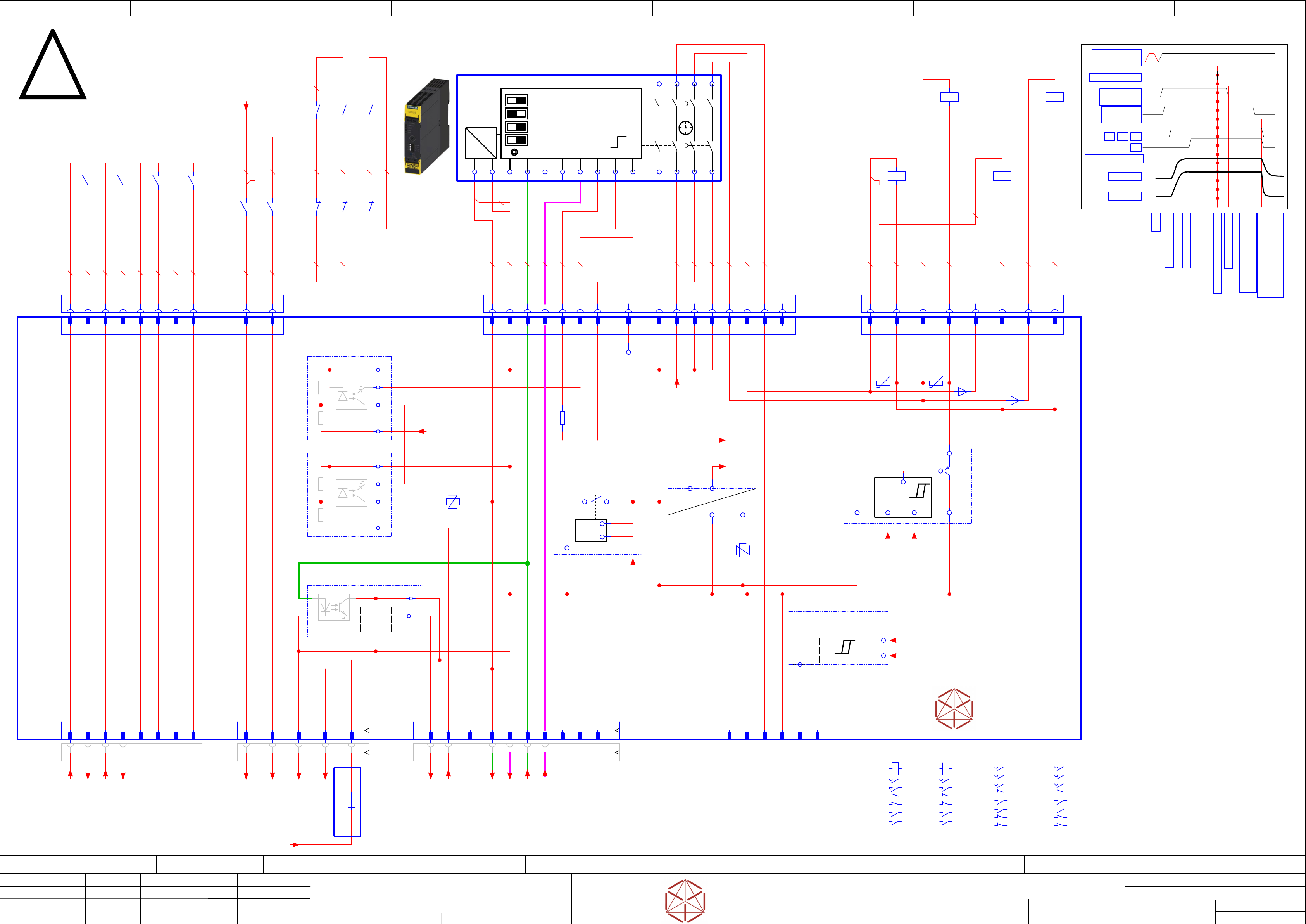
LOGIC
=~
=
+ -
+ -
+ -
+ -
1 | Autostart/Monitored Start
1 | A
utostart/Monitored Start
1 | Autostart/Monitored Start
1 | Autostart/Monitored Start
2 | Cross Fault Detection Off/On
2 | Cr
oss Fault Detection Off/On
2 | Cross Fault Detection Off/On
2 | Cross Fault Detection Off/On
3 | 2 single ch. sensors / 1 double channel Sensor
3 | 2 single ch. sensors / 1 double channel S
ensor
3 | 2 single ch. sensors / 1 double channel Sensor
3 | 2 single ch. sensors / 1 double channel Sensor
4 | Startup Test Yes/No
4 | Startup T
est Yes/No
4 | Startup Test Yes/No
4 | Startup Test Yes/No
SET / RESET
SET / RESET
SET / RESET
SET / RESET
T
T
T
T
- not used -
Parts shown at this page
are for safety related purposes.
To be replaced by
original parts only!
03108631-010301le3
Timing chart
S
S
S
S
Start
Start
Start
Start
Precharge done
Precharge done
Precharge done
Precharge done
Emergency STOP event
Emergency STOP event
Emergency STOP event
Emergency STOP event
K1,K2, K3, K4 off delay;
K1,K2, K3, K4 off delay;
K1,K2, K3, K4 off delay;
K1,K2, K3, K4 off delay;
Discharge external Cap
Discharge external Cap
Discharge external Cap
Discharge external Cap
-->Power off
-->P
ower off
-->Power off
-->Power off
Safety relais off
Safety relais off
Safety relais off
Safety relais off
Safety relaais off delay
Safety relaais off delay
Safety relaais off delay
Safety relaais off delay
> 100 ms; <180 ms
> 100 ms; <180 ms
> 100 ms; <180 ms
> 100 ms; <180 ms
Precharge start
Precharge start
Precharge start
Precharge start
DC 300 V
DC 300 V
DC 300 V
DC 300 V
DC 160 V
DC 160 V
DC 160 V
DC 160 V
K2
K2
K2
K2
POWER_ENABLE
POWER_ENABLE
POWER_ENABLE
POWER_ENABLE
K1
K1
K1
K1 K4
K4
K4
K4K3
K3
K3
K3
PCC output
PCC output
PCC output
PCC output
delayed
dela
yed
delayed
delayed
PCC output
PCC output
PCC output
PCC output
not delayed
not dela
yed
not delayed
not delayed
EMG_Loop_OK
EMG_Loop_OK
EMG_Loop_OK
EMG_Loop_OK
SW_CTRL_ON
SW_CTRL_ON
SW_CTRL_ON
SW_CTRL_ON
Start
Start
Start
Start
Safety_Loop 1&2
Saf
ety_Loop 1&2
Safety_Loop 1&2
Safety_Loop 1&2
to Distributor -X22
to Distributor -
X22
to Distributor -X22
to Distributor -X22
4x Safety Loop Extern
4x Saf
ety Loop Extern
4x Safety Loop Extern
4x Safety Loop Extern
seperated circuit diagram
ITS4141
Load-switch
&
-F1
-F2
24V_PCC
24V_PCC
24V_PCC
24V_PCC
&
GND_Safety
GND_Saf
ety
GND_Safety
GND_Safety
ITS4141
Load-switch
&
A1
INK
IN1
IN2
A2
13
23
37
47
INF
INS
38
48
T2
T1
PAR
-K5
-K5
-K5
-K5
Safety relay 2-chanel
Saf
ety relay 2-chanel
Safety relay 2-chanel
Safety relay 2-chanel
Safety relay 2NO S=0, 2NO, S=1 (50 ms - 3000ms)
Saf
ety relay 2NO S=0, 2NO, S=1 (50 ms - 3000ms)
Safety relay 2NO S=0, 2NO, S=1 (50 ms - 3000ms)
Safety relay 2NO S=0, 2NO, S=1 (50 ms - 3000ms)
SIE.3SK1121-2CB41
03114826
14
24
Safety Relais connect
-X100.CSB
-
X100.CSB
-X100.CSB
-X100.CSB
-K1
-K1
-K1
-K1
Relay Safety
300V, 160V
A1
A2
A1 A2
1 2
3 4
2221
/116.2
3132
/116.2
1413
4443
/116.1
SIE.3TC4417-0AB4
-K3
-K3
-K3
-K3
Relay Safety
42V, 24V
A1
A2
1 2
3 4
5 6
2221
5453
/116.0
6463
/116.0
7271
8281
/116.2
EAT.DILM17-01(RDC24)
-K4
-K4
-K4
-K4
Relay
Pre-charge
300V, 160V
A1
A2
1 2
3 4
5 6
2122
/116.2
5453
/116.1
6463
/116.1
7271
8281
EAT.DILM17-01(RDC24)
OUT2_ND
DC 24V Safety controlled PL=d
3
GND Safety
8
Loop-CLSD
A5
Loop2-IN
B1
nc
B2
Loop1_IN
A3
Loop ext 1-1
1
Loop ext 1-2
2
Loop ext 2-1
3
Loop ext 2-2
4
Loop ext 3-1
5
Loop ext 3-2
6
Loop ext 4-1
7
Loop ext 4-2
8
A5 B18
GND Safety
2
GND Safety
4
1
1
2
2
3
3
4
4
5
5
6
6
7
7
8
8
9
9
10
10
CH2-OK
16
16
CH1-OK
15
15 5
24V-PCC
B5
24V-PCC
B6
B5
nc
1
PPWR-present
5
nc
6
-A2
-
A2
-A2
-A2
Safety breaker
Saf
ety breaker
Safety breaker
Safety breaker
PCB Pre-/discharge assembly
PCB Pr
e-/discharge assembly
PCB Pre-/discharge assembly
PCB Pre-/discharge assembly
-X28.CSB
-
X28.CSB
-X28.CSB
-X28.CSB
AuxContacts
-X28
-
X28
-X28
-X28
AuxContacts in
-X27.CSB
-
X27.CSB
-X27.CSB
-X27.CSB
Safety
contactor
-X30
-
X30
-X30
-X30
Safety
Loop extern
-X24B
-X24B
-X24B
-X24B
Safety
control signals
-X24B.CSB
-X24B.CSB
-X24B.CSB
-X24B.CSB
Safety control
signals to FDB
-W10
-X29.CSB
-X29.CSB
-X29.CSB
-X29.CSB
Safety Loop
& Signals
extern
-W11.1
-X29
-
X29
-X29
-X29
Safety Loop
& Signals
-X31
-
X31
-X31
-X31
Auxiliary
(RFU signals)
-K2
-K2
-K2
-K2
Relay Safety
300V, 160V;
Power enable
A1
A2
A1 A2
1 2
3 4
2221
/116.2
3231
/116.2
1413
4344
/116.2
SIE.3TC4417-0AB4
START_SIG
Safety Start
Signal input
A6
A6
0,75 YE0,75 YE
-K3
-K3
-K3
-K3
81
82
-K4
-K4
-K4
-K4
22
21
-K1
-K1
-K1
-K1
21
22
-K1
-K1
-K1
-K1
32
31
-K2
-K2
-K2
-K2
21
22
-K2
-K2
-K2
-K2
31
32
0,75 YE
0,75 YE 0,75 YE
0,75 YE
0,75 YE
24V0
Safety unit
5
24V_PCC
7
7
nc
A4
nc
B3
nc
B4
B2 B3 B4A4 B6 A3
0,5 PK
0,5 WH
0,5 PK
0,5 PK
0,5 WH
0,5 WH
0,5 PK
0,5 YE
-K3
-K3
-K3
-K3
63
64
-K3
-K3
-K3
-K3
53
54
-K4
-K4
-K4
-K4
53
54
-K1
-K1
-K1
-K1
43
44
0,5 YE
0,5 YE
-K4
-K4
-K4
-K4
63
64
0,5 YE
0,5 YE
0,5 YE
0,5 YE
0,5 BN
0,5 BN
0,5 YE
0,5 YE
0,5 YE
0,5 YE
-K2
-K2
-K2
-K2
44
43
0,5 BN
0,5 WH
0,5 YE
0,5 YE
0,5 YE
0,5 BN
0,5 PK
0,5 PK
0,5 PK
0,5 YE
0,5 BN
0,5 BN
0,5
BN
-X30.CSB
-
X30.CSB
-X30.CSB
-X30.CSB
Safety
Loop Extern
-W11.2
1 2 3 4 5 6 7 8
-F11
-F11
-F11
-F11
Supp1_SSK_RDY
6,3A
6,3A
6,3A
6,3A
A2 Fuse & Distripution
1 2 3 4 5 6 7 8
nc
9 10 11
nc
12 13 14 15 16
nc
15
OUT2_ND
13
OUT2_D
16
nc
1
K1-A1
1 2
2
GND
8
8
GND
14
OUT1_D
6
6
GND
5
5
A3-K1
7
7
K4-A1
-X100
-
X100
-X100
-X100
Safety relais connect
-X27
-
X27
-X27
-X27
Safety
contactor
3 4
3
K2-A1
4
GND/K5
-R42
60VAC(100mW)
-R43
60VAC(100mW)
-D18
1
24V_PCC
2
GND
3
Loop1_IN
4
Loop2_IN
5
T2
6
START
7
TestLoopIn
8
nc
-R128
0R
Test_loop_IN
+
+
-
-K1
-K1
-K1
-K1
Safety loop
closed signal
24V0
L_CLSD
9
24V0
10
24Vext
11
24V0
12
24V0
-D50
-P300.pbc
-P300.pbc
-P300.pbc
-P300.pbc
Voltage-Trigger
300V precharge bypass control
Out
GND
24V0
24V.Safe
24V
.Safe
24V.Safe
24V.Safe
Safe DC
internal supply
24VSafe
24V0
-K2
-K2
-K2
-K2 Start_loop
-
+
+
in
out
GND
DIAGN_K_N
-K3
-K3
-K3
-K3 Start_loop
-
+
+
in
out
GND
START_SIG
24V_PCC
24V_PCC
24V_PCC
24V_PCC
PCC supply
undervoltage lockout
OUT
24V_PCC
IN
24V0
DIAG
U_Mon
-Out
-PPWR.PRESENT
-PPWR.PRESENT
-PPWR.PRESENT
-PPWR.PRESENT
Voltage-Trigger
300V/160V PPWR-present
(300V > 60V & 160V > 60V)
P300V
P160V
-DI0_Safety_Loop_OK
+DI/117.1
-Loop2-IN
-Loop2-IN
-Loop2-IN
-Loop2-IN
+DI/117.1
-Loop1_OUT
-Loop1_OUT
-Loop1_OUT
-Loop1_OUT
+DI/117.1
-Safety_Start_SSK
+DI/117.1
-Loop2_OUT
-Loop2_OUT
-Loop2_OUT
-Loop2_OUT
+DI/117.1
-Loop1-IN
-Loop1-IN
-Loop1-IN
-Loop1-IN
+DI/117.1
==+-24V_F12_Aux
-Safety_Loop1_ext.in
+DI/117.2
-Safety_Loop1_ext.out
+DI/117.2
-Safety_Loop2_ext.in
+DI/117.2
-Safety_Loop2_ext.out
+DI/117.2
-GND_1
-CH1-OK
-CH2-OK
-PCC-POWER-OK
DC 24 V
from Power Supply PS4
24V-Supply
-P300V
-P160V
VDIFFMON1
300V
VDIFFMON2
160V
24VSafe
Safe supply
P_GND
Power Ground
DIAGN_K_N
DIAGN_RD_N
electric_schematic SIPLACE TX_V2
electric_schematic SIPLACE TX_V2
electric_schematic SIPLACE TX_V2
electric_schematic SIPLACE TX_V2
90012669-010501LE3
Replaced by
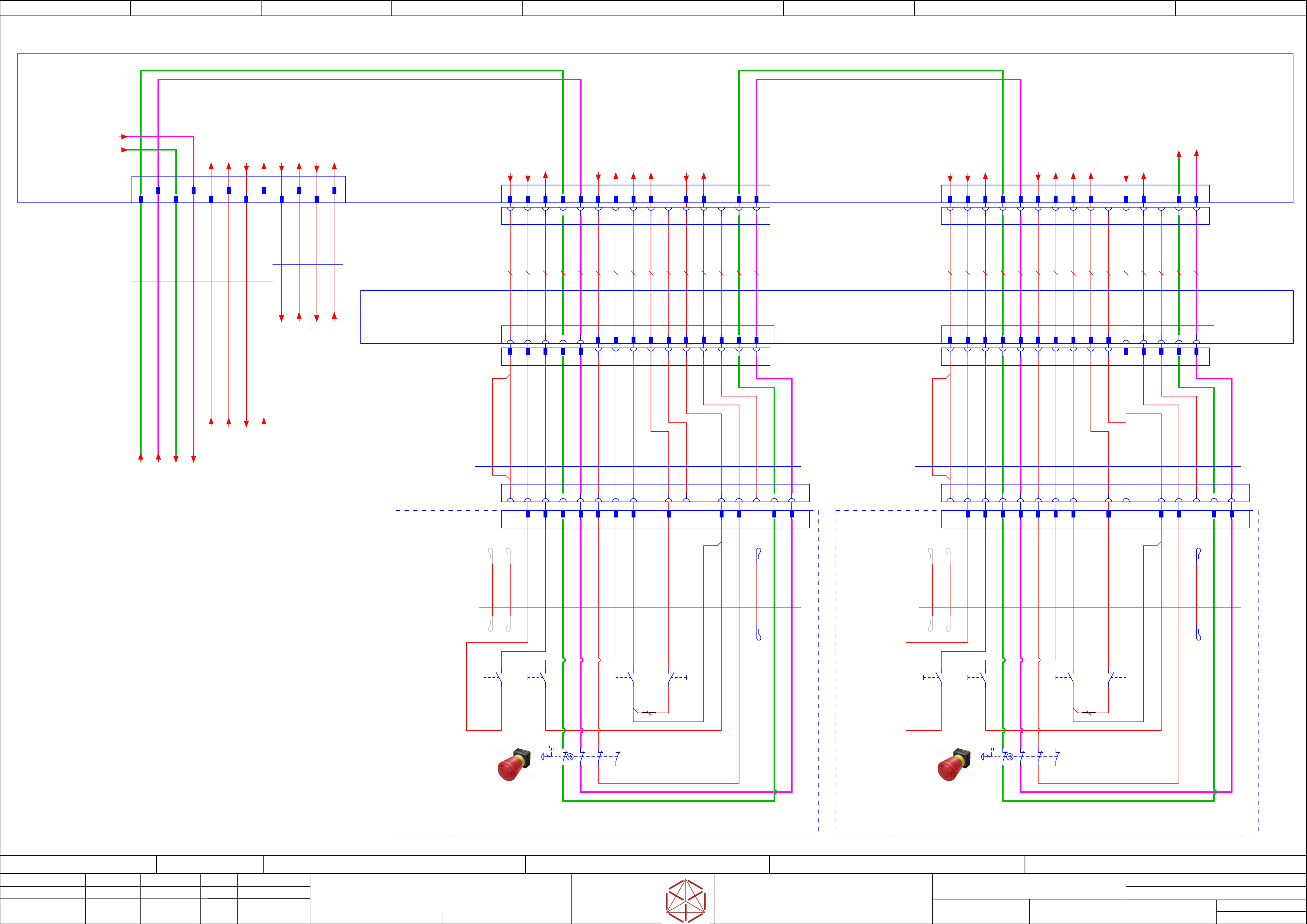
Safety-Loop overview
Safety-Loop overview
Safety-Loop overview
Safety-Loop overview
Emergency-Stop Start/Stop-Buton
Emer
gency-Stop Start/Stop-Buton
Emergency-Stop Start/Stop-Buton
Emergency-Stop Start/Stop-Buton
Replaced by
Weitergabe sowie Vervielfältigung dieser Unterlage, Verwertung und
Mitteilung des Inhalts nicht gestattet, soweit nicht ausdrücklich zugestanden.
Proprietary Data, company confidential.
All rights reserved
Copying of this document, giving it to others and the use or
communication of the contents thereof, are forbidden without express authority.
Doc. No.
00 01 02 03 04 05 06 07 08 09
Privileged business information.
Do not release
Offenders are liable to payment of damages. All rights are reserved in the
event of the grant or the registration of a utility model or design.
Zuwiederhandlungen verpflichten zu Schadenersatz. Alle Rechte vorbehalten,
insbesondere für den Fall der Patenterteilung oder GM-Eintragung vorbehalten.
Page:
Function: Emergency
==EMG=TX_EMG+DI/117
drawing number:
90012669- EMG
Emergency Loop Documentation
Emer
gency Loop Documentation
Emergency Loop Documentation
Emergency Loop Documentation
GmbH & Co KG
ASM
Assembly Systems
Copyright reserved
Ed.
Original
Pingist
Date
Date
Modification
Appr
07.02.2018
Name
Size DIN A2
Sheet
117
/
3
Bridge-J1 Bridge-J1
3 4 5 6 7 8 9 10 11 12 13 14 15 1 2 3 4 5 6 7 8 9 10 11 12 13 14 15
Safety_Loop
Safety_Loop
Safety_Loop
Safety_Loop
to Connector
to Connector
to Connector
to Connector
X25
X25
X25
X25
Safety_Loop 1&2
Saf
ety_Loop 1&2
Safety_Loop 1&2
Safety_Loop 1&2
to Conntactor_Safety_Breaker CSB
to Conntactor_Saf
ety_Breaker CSB
to Conntactor_Safety_Breaker CSB
to Conntactor_Safety_Breaker CSB
X29
X29
X29
X29
Safety_Loop extern
Saf
ety_Loop extern
Safety_Loop extern
Safety_Loop extern
Optional Machine
Optional Machine
Optional Machine
Optional Machine
seperated circuit diagram
Safety-Loop
Safety-Loop
Safety-Loop
Safety-Loop
from Connector -X36
f
rom Connector -X36
from Connector -X36
from Connector -X36
3 4 5 6 7 8 9 10 11 12 13 14 15
1 2 3 4 5 6 7 8 9 10 11 12 13 14 15
-X1.CE2
-
X1.CE2
-X1.CE2
-X1.CE2
1 2 3 4 5 6 7 8 9 10 11 12 13 14 15
1 2 3 4 5 6 7 8 9 10 11 12 13 14 15
-X1.CE1
-
X1.CE1
-X1.CE1
-X1.CE1
1 2
-DI
-DI
-DI
-DI
Distributor
Distributor
Distributor
Distributor
Control elements 2
Contr
ol elements 2
Control elements 2
Control elements 2
(GCU side)
(GCU side)
(GCU side)
(GCU side)
Start / Stop 2
Start / Stop 2
Start / Stop 2
Start / Stop 2
-X24
-
X24
-X24
-X24
Mini MATE-N-LOK Socket 15-pin
TYCO.172163-1
1 2 3 4 5 6 7 8 10 13
Control elements 1
Contr
ol elements 1
Control elements 1
Control elements 1
(Power supply side)
(P
ower supply side)
(Power supply side)
(Power supply side)
Start / Stop 1
Start / Stop 1
Start / Stop 1
Start / Stop 1
-X23
-
X23
-X23
-X23
Mini MATE-N-LOK Socket 15-pin
TYCO.172163-1
10 139 11 12 14 151 2 3 4 5 6 7 8 9 11 12 14 15
Control elements 2
Control elements 2
Control elements 2
Control elements 2
(GCU side)
(GCU side)
(GCU side)
(GCU side)
Start / Stop 2
Start / Stop 2
Start / Stop 2
Start / Stop 2
-X24
-
X24
-X24
-X24
Mini MATE-N-LOK Socket 15-pin
TYCO.172163-1
1 2 3 4 5 6 7 8
Control elements 1
Control elements 1
Control elements 1
Control elements 1
(Power supply side)
(Power supply side)
(Power supply side)
(Power supply side)
Start / Stop 1
Start / Stop 1
Start / Stop 1
Start / Stop 1
-X23
-
X23
-X23
-X23
Mini MATE-N-LOK Socket 15-pin
TYCO.172163-1
9 11 12 14 156 7 8 91310 10
-X23.DI
-
X23.DI
-X23.DI
-X23.DI
TYCO.172171-1
Mini MATE-N-LOK Plug 15-pin
10 1511 139 12 141 2 3 4 5 6 7 8
-X24.DI
-
X24.DI
-X24.DI
-X24.DI
TYCO.172171-1
Mini MATE-N-LOK Plug 15-pin
1 2 3 4 5 6 7 8 10 1511 139 12 14
1 2 3 54 11 13 1412 15
-DIC
-DIC
-DIC
-DIC
Distributor TX
Distributor TX
Distributor TX
Distributor TX
Connector field
Safety-Loop & Signals
Saf
ety-Loop & Signals
Safety-Loop & Signals
Safety-Loop & Signals
from
f
rom
from
from
Power supply SMPS
Power supply SMPS
Power supply SMPS
Power supply SMPS
#-DI-X22
#-DI
-X22
#-DI-X22
#-DI-X22
DYNAMIC D-2100D Tab 2x6-pin X key panel type
TYCO.1-1318114-6
A1
B1
A2
B2
A3 A4
B3 B4
A5 A6
B5 B6
570 mm
6x0,61
Single core UL/cUL Style
03112103
03112103
03112103
03112103 -02
-02
-02
-02
-W11.1
-
W11.1
-W11.1
-W11.1
620 mm
4x0,61
Single core UL/cUL Style
03112103
03112103
03112103
03112103
-02
-02
-02
-02
-W11.2
-
W11.2
-W11.2
-W11.2
20 AWG WH
20 AWG YE
20 AWG YE
20 AWG YE
20 AWG YE
20 AWG BN
20 AWG BN
20 AWG YE
20 AWG YE
20 AWG WH
20 AWG YE
20 AWG YE
20 AWG BN
20 AWG BN
20 AWG YE
20 AWG YE
20 AWG YE
20 AWG YE
20 AWG YE
20 AWG YE
20 AWG YE
20 AWG YE
20 AWG YE
20 AWG YE
Safety_Loop1 >>
Safety_Loop2 >>
Safety_Loop1 >>
Safety_Loop2 >>
20 AWG YE
20 AWG YE
-X24.DIC
-
X24.DIC
-X24.DIC
-X24.DIC
-X23.DIC
-
X23.DIC
-X23.DIC
-X23.DIC
1 2 3 4 5 7 86 11 13
10 15
3610 mm
16x0,34
UNITRONIC® LiYY A
03148021
03148021
03148021
03148021
-W41
-W41
-W41
-W41
11 13
10 15 1 2 3 4 5 7 86
1 2 3 4 5 6 7 89 12 14
9 12 14
WH
BN
GN
YE
GY
PK
BU
RD
BK
VT
GYPK
RDBU
WHGN
BNGN
WHYE
YEBN
2950 mm
16x0,34
UNITRONIC® LiYY A
03148022
03148022
03148022
03148022
-W42
-
W42
-W42
-W42
WH
BN
GN
YE
BU
RD
BK
VT
GYPK
RDBU
WHGN
YEBN
11
1310 159 12 14
6 7 8 1091 2 3 4 5 11 12 13 14 15
Location-2
Location-2
Location-2
Location-2
03110694
03110694
03110694
03110694
Control elements
Contr
ol elements
Control elements
Control elements
EmergencyStop/Start/Stop
Emer
gencyStop/Start/Stop
EmergencyStop/Start/Stop
EmergencyStop/Start/Stop
-U2
-U2
-U2
-U2
5
Safety_Loop2_IN
6
24V
1
12
Emergency_Stop
14
Safety_Loop1_OUT
15
Safety_Loop2_OUT
2
SW_Control_on
3
Start_Button
7
S_Start_Button
8
S_Stop_Button
11
24V
9
S_Button_COTi
21
22
21
22
-S2.2
-
S2.2
-S2.2
-S2.2
2NC
11
12
500 mm
16x0,34
UNITRONIC® LiYY A
-W1
-
W1
-W1
-W1
BN
GN
YE
BU
RD
BK
VT
GYPK
RDBU
WH
YEBN
-nc
-nc
-S2.1
-
S2.1
-S2.1
-S2.1
2NC
EmergencyStop
Emer
gencyStop
EmergencyStop
EmergencyStop
11
12
-nc
WHGN
-S3
-S3
-S3
-S3
1NO
Stop
Stop
Stop
Stop
3
4
-S1.1
-
S1.1
-S1.1
-S1.1
1NO
Start
Start
Start
Start
3
4
-S1.2
-
S1.2
-S1.2
-S1.2
1NO
Start
Start
Start
Start
3
4
-nc
-nc
-S4
-S4
-S4
-S4
1NO
COTi
CO
Ti
COTi
COTi
3
4
-X1.CE
-X1.CE
-X1.CE
-X1.CE
BK (J1) 0,34
400 mm
-nc
Location-1
Location-1
Location-1
Location-1
03110694
03110694
03110694
03110694
Control elements
Contr
ol elements
Control elements
Control elements
EmergencyStop/Start/Stop
Emer
gencyStop/Start/Stop
EmergencyStop/Start/Stop
EmergencyStop/Start/Stop
-U1
-U1
-U1
-U1
5
Safety_Loop2_IN
6
24V
4
Safety_Loop1_IN
12
Emergency_Stop
14
Safety_Loop1_OUT
15
Safety_Loop2_OUT
2
SW_Control_on
3
Start_Button
7
S_Start_Button
8
S_Stop_Button
11
24V
9
S_Button_COTi
21
22
21
22
-S2.2
-
S2.2
-S2.2
-S2.2
2NC
11
12
500 mm
16x0,34
UNITRONIC® LiYY A
-W1
-
W1
-W1
-W1
BN
GN
YE
GY
PK
BU
RD
BK
VT
GYPK
RDBU
BNGN
WHYE
WH
-nc
4
Safety_Loop1_IN
-S2.1
-
S2.1
-S2.1
-S2.1
2NC
EmergencyStop
Emer
gencyStop
EmergencyStop
EmergencyStop
11
12
-nc
WHGN
-S3
-S3
-S3
-S3
1NO
Stop
Stop
Stop
Stop
3
4
-S1.1
-
S1.1
-S1.1
-S1.1
1NO
Start
Start
Start
Start
3
4
-S1.2
-
S1.2
-S1.2
-S1.2
1NO
Start
Start
Start
Start
3
4
-nc
-nc
-S4
-S4
-S4
-S4
1NO
COTi
CO
Ti
COTi
COTi
3
4
-X1.CE
-X1.CE
-X1.CE
-X1.CE
BK (J1) 0,34
400 mm
-nc
YEBN
20 AWG YE
20 AWG YE
20 AWG YE
20 AWG YE
GY
PK
BNGN
WHYE
GY
PK
BNGN
WHYE
-Start_Button_2
(SSK)
-DI12_Stop_Button_2
-DI2_EMG_Stop_2
-DI11_Start_Button_2
-DO1_Control_ON_2
-DI16_Button_COTi_2
-GND_3b
-24V_12c
-24V_12d
-24V_12b
-DI9_Stop_Button_1.1
-DI14_EMG_Stop_1
-DI8_Start_Button_1.1
-DO1_Control_ON_1
-DI24_Button_COTi_1
-GND_3a
-24V_12a
-Start_Button_1
(SSK)
==DI+-Safety_Loop1
==DI+-
Safety_Loop1
==DI+-Safety_Loop1
==DI+-Safety_Loop1
-DI-X36:11 /119.09
-DI13_PWR_enabled
-Safety_Start
(SSK)
-24V_S_19a
==DI+-Safety_Loop2
==DI+-
Safety_Loop2
==DI+-Safety_Loop2
==DI+-Safety_Loop2
-DI-X36:12 /119.09
-DI0_Safety_Loop_OK
-Safety_Loop1_ext.in
-DI-X28:8 /119.02
-Safety_Loop1_ext.out
-DI-X28:9 /119.02
-Safety_Loop2_ext.in
-DI-X29:8 /119.05
-Safety_Loop2_ext.out
-DI-X29:9 /119.05
-Safety_Loop1_ext.in
-X30.CSB:1 +CSB/116.00
-Safety_Loop1_ext.out
-X30.CSB:2 +CSB/116.00
-Safety_Loop2_ext.in
-X30.CSB:3 +CSB/116.00
-Safety_Loop2_ext.out
-X30.CSB:4 +CSB/116.00
-Safety_Loop1.3
-Safety_Loop1.3
-Safety_Loop1.3
-Safety_Loop1.3
-DI-X25:4 /118.01
-Safety_Loop2.3
-Safety_Loop2.3
-Safety_Loop2.3
-Safety_Loop2.3
-DI-X25:5 /118.01
-Loop2_OUT
-Loop2_OUT
-Loop2_OUT
-Loop2_OUT
-X29.CSB:B6 +CSB/116.03
-DC24V_S_DIS
-DI13_PWR_enabled
-Loop2-IN
-Loop2-IN
-Loop2-IN
-Loop2-IN
-X29.CSB:B1 +CSB/116.04
-DI0_Safety_Loop_OK
-X29.CSB:A5 +CSB/116.03
-Safety_Start_SSK
-X29.CSB:A6 +CSB/116.03
-Loop1_OUT
-Loop1_OUT
-Loop1_OUT
-Loop1_OUT
-X29.CSB:B5 +CSB/116.03
[Beginn]
[B
eginn]
[Beginn]
[Beginn]
-Loop1-IN
-Loop1-IN
-Loop1-IN
-Loop1-IN
-X29.CSB:A3 +CSB/116.04
[End]
[End]
[End]
[End]
2
-nc
electric_schematic SIPLACE TX_V2
electric_schematic SIPLACE TX_V2
electric_schematic SIPLACE TX_V2
electric_schematic SIPLACE TX_V2
90012669-010501LE3
Replaced by
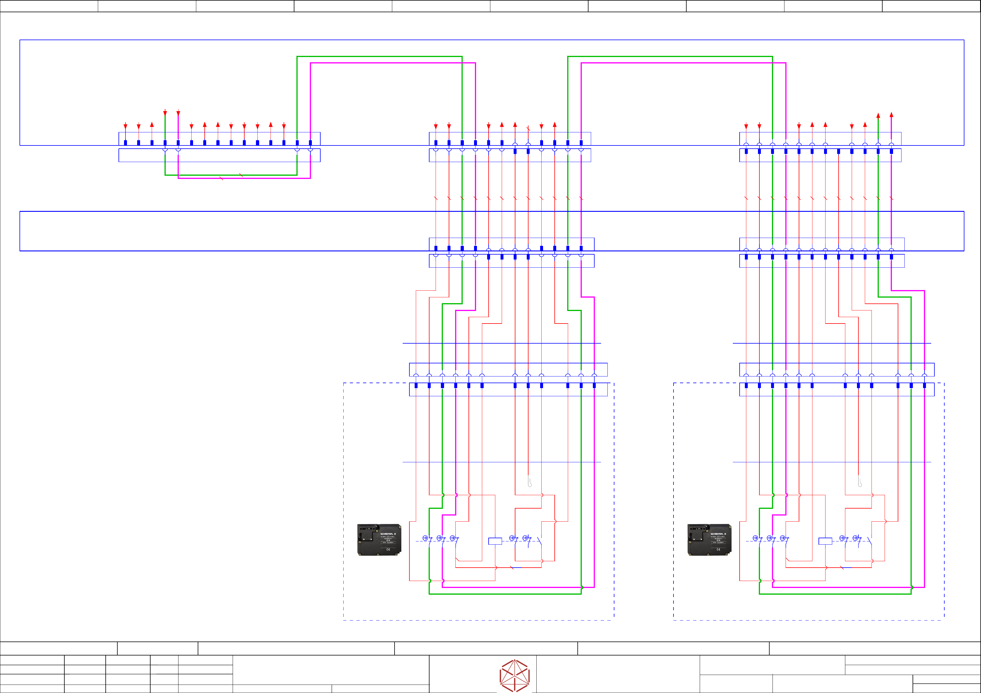
Safety-Loop overview
Safety-Loop overview
Safety-Loop overview
Safety-Loop overview
Hood-switch
Hood-swi
tch
Hood-switch
Hood-switch
Replaced by
Weitergabe sowie Vervielfältigung dieser Unterlage, Verwertung und
Mitteilung des Inhalts nicht gestattet, soweit nicht ausdrücklich zugestanden.
Proprietary Data, company confidential.
All rights reserved
Copying of this document, giving it to others and the use or
communication of the contents thereof, are forbidden without express authority.
Doc. No.
00 01 02 03 04 05 06 07 08 09
Privileged business information.
Do not release
Offenders are liable to payment of damages. All rights are reserved in the
event of the grant or the registration of a utility model or design.
Zuwiederhandlungen verpflichten zu Schadenersatz. Alle Rechte vorbehalten,
insbesondere für den Fall der Patenterteilung oder GM-Eintragung vorbehalten.
Page:
Function: Emergency
==EMG=TX_EMG+DI/118
drawing number:
90012669- EMG
Emergency Loop Documentation
Emer
gency Loop Documentation
Emergency Loop Documentation
Emergency Loop Documentation
GmbH & Co KG
ASM
Assembly Systems
Copyright reserved
Ed.
Original
Pingist
Date
Date
Modification
Appr
07.02.2018
Name
Size DIN A2
Sheet
118
/
3
1 2 3 4 5 6 7 8 9 10 11 12 1 2 3 4 5 6 7 8 9 10 11 12
Safety_Loop
Saf
ety_Loop
Safety_Loop
Safety_Loop
from Connector
f
rom Connector
from Connector
from Connector
X24
X24
X24
X24
Safety_Loop
Saf
ety_Loop
Safety_Loop
Safety_Loop
to Connector
to Connector
to Connector
to Connector
X28
X28
X28
X28
seperated circuit diagram
3 4 5 6 7 8 9 10 11 12
1 2 3 4 5 6 7 8 9 10 11 12
-X1.HS2
-
X1.HS2
-X1.HS2
-X1.HS2
1 2 3 4 5 6 7 8 9 10 11 12
-X1.HS1
-
X1.HS1
-X1.HS1
-X1.HS1
1 2 3 4 5 6 7 8 9 10 11 12 1 2
-DI
-DI
-DI
-DI
Distributor
Security Loop
S
ecurity Loop
Security Loop
Security Loop
Control elements Hood 1
Contr
ol elements Hood 1
Control elements Hood 1
Control elements Hood 1
-X26
-
X26
-X26
-X26
Mini MATE-N-LOK Socket 12-pin
TYCO.172162-1
1 2 3 4 5 6 9 10 11 127 8
Blind_Socket
Security Loop
S
ecurity Loop
Security Loop
Security Loop
Control elements Hood 1
Contr
ol elements Hood 1
Control elements Hood 1
Control elements Hood 1
-X26
-
X26
-X26
-X26
Mini MATE-N-LOK Socket 12-pin
TYCO.172162-1
1 2 3 4 9 10 11 127 8
-X26.DI
-
X26.DI
-X26.DI
-X26.DI
TYCO.172170-1
Mini MATE-N-LOK Plug 12-pin
1 2 3 4 5 6 10 129 117 8
5 6
Security Loop
S
ecurity Loop
Security Loop
Security Loop
Control elements Hood 2
Contr
ol elements Hood 2
Control elements Hood 2
Control elements Hood 2
-X27
-
X27
-X27
-X27
Mini MATE-N-LOK Socket 12-pin
TYCO.172162-1
1 2 3 4 5 6 10 129 1187
Security Loop
S
ecurity Loop
Security Loop
Security Loop
Control elements Hood 2
Contr
ol elements Hood 2
Control elements Hood 2
Control elements Hood 2
-X27
-
X27
-X27
-X27
Mini MATE-N-LOK Socket 12-pin
TYCO.172162-1
1 2 3 4 5 6 10 129 117 8
-X27.DI
-
X27.DI
-X27.DI
-X27.DI
TYCO.172170-1
Mini MATE-N-LOK Plug 12-pin
1 2 3 4 5 10 126 7 8 9 11
-DIC
-DIC
-DIC
-DIC
Distributor TX
Distributor TX
Distributor TX
Distributor TX
Connector field
-X25.1
-
X25.1
-X25.1
-X25.1
Jumper connector
Jumper connector
Jumper connector
Jumper connector
TYCO.172171-1
Mini MATE-N-LOK Plug 15-pin
109 14 151311
-X25
-X25
-X25
-X25
Service- and Test-Interface
S
ervice- and Test-Interface
Service- and Test-Interface
Service- and Test-Interface
TYCO.172163-1
Mini MATE-N-LOK Socket 15-pin
11 13 1512 14
1 2 3 7 86 12
0,5 YE
0,5 YE
91 2 3 4 5 6 7 8
4 5
10
20 AWG WH
20 AWG YE
20 AWG BN
20 AWG BN
20 AWG YE
20 AWG YE
20 AWG YE
20 AWG YE
AWG20 WH
AWG20 BN
AWG20 BN
AWG20 YE
AWG20 YE
20 AWG YE
20 AWG YE
AWG20 YE
Safety_Loop1 >>
Safety_Loop2 >>
Safety_Loop1 >>
Safety_Loop2 >>
-X27.DIC
-
X27.DIC
-X27.DIC
-X27.DIC
-X26.DIC
-
X26.DIC
-X26.DIC
-X26.DIC
1 2 3 4
1 2 3 4 5
10 12
6 10 12 1 2 3 4 5 6
3960 mm
12x0,34
UNITRONIC® LiYY A
03148023
03148023
03148023
03148023
-W43
-
W43
-W43
-W43
WH
BN
GN
YE
GY
PK
BU
RD
1
2 3 4 5 10 126 7 8 9 119 11
7 8 9 11
VT
BK
10
127 8 9 11
3480 mm
12x0,34
UNITRONIC® LiYY A
03148024
03148024
03148024
03148024
-W44
-
W44
-W44
-W44
WH
BN
GN
PK
BU
RD
VT
BK
GYPK
7
85 6
Location-1
Hood switch TX
Hood switch TX
Hood switch TX
Hood switch TX
03110691
03110691
03110691
03110691
-S1
-
S1
-S1
-S1
AZM 161CC-12/03RKA-024
AZM 161CC
-12/03RKA-024
AZM 161CC-12/03RKA-024
AZM 161CC-12/03RKA-024
Drawn contact position: - Hood locked
- Bolt locked
11
12
21
22
41
42
51
52
71
72
63
64
1
GND
2
Hood_Lock
3
Safety_Loop1_IN
4
Safety_Loop2_IN
5
24V
6
S_Hood
9
24V
10
S_Hood
11
Safety_Loop1_OUT
12
Safety_Loop2_OUT
7
Hood_Lock_on
8
nc
-S1
Lock
Lock
Lock
Lock
A1
A2
/118.05
BK (J1) 0,34
50 mm
Bridge-J1
600 mm
12x0,34
UNITRONIC® LiYY A
-W1
-
W1
-W1
-W1
WH
BN
GN
YE
GY
PK
BU
RD
VT
BK
GYPK
RDBU
-X1.HS
-X1.HS
-X1.HS
-X1.HS
Location-2
Hood switch TX
Hood switch TX
Hood switch TX
Hood switch TX
03110691
03110691
03110691
03110691
-S2
-
S2
-S2
-S2
AZM 161CC-12/03RKA-024
AZM 161CC
-12/03RKA-024
AZM 161CC-12/03RKA-024
AZM 161CC-12/03RKA-024
Drawn contact position: - Hood locked
- Bolt locked
11
12
21
22
41
42
51
52
71
72
63
64
1
GND
2
Hood_Lock
3
Safety_Loop1_IN
4
Safety_Loop2_IN
5
24V
6
S_Hood
9
24V
10
S_Hood
11
Safety_Loop1_OUT
12
Safety_Loop2_OUT
8
nc
-S1
Lock
Lock
Lock
Lock
A1
A2
/118.08
BK (J1) 0,34
50 mm
Bridge-J1
600 mm
12x0,34
UNITRONIC® LiYY A
-W1
-
W1
-W1
-W1
WH
BN
GN
PK
BU
RD
VT
BK
-X1.HS
-X1.HS
-X1.HS
-X1.HS
7
Hood_Lock_on
20 AWG YE
20 AWG YE
20 AWG YE
20 AWG YE
20 AWG YE
20 AWG YE
20 AWG YE
20 AWG YE
YE
GY
GYPK
RDBU
YE
GY
RDBU
GYPK
RDBU
-24V_13a
-S_Hood1
(K1, DI25)
-GND_3c
-DO5_Hood_Lock1
-24V_13b
-S_Hood1_FCU
-DI-X28:3 /119.02
-DI27_Hood1_Lock_on
-24V_13c
-S_Hood2
(K2, DI17)
-GND_3d
-DO4_Hood_Lock2
-24V_13d
-S_Hood2_FCU
-DI-X29:3 /119.04
-Safety_Loop1.6
-Safety_Loop1.6
-Safety_Loop1.6
-Safety_Loop1.6
-DI-X28:4 /119.02
-Safety_Loop2.6
-Safety_Loop2.6
-Safety_Loop2.6
-Safety_Loop2.6
-DI-X28:5 /119.02
-DI19_Hood2_Lock_on
-Start_Button_3
(SSK)
-24V_18b
(F3)Service
-GND_9c
-DO1_Control_ON_3
-DO16_Service
-DI15_EMG_Stop_Service
-DI9_Stop_Button_1.2
-DI8_Start_Button_1.2
-DO17_Service
-24V_S_20c
-DO18_Service
-Safety_Loop1.3
-Safety_Loop1.3
-Safety_Loop1.3
-Safety_Loop1.3
-DI-X24:14 /117.09
-Safety_Loop2.3
-Safety_Loop2.3
-Safety_Loop2.3
-Safety_Loop2.3
-DI-X24:15 /117.09