00198460-01_DC_SIPLACE_TX-EditionV2_DE+EN.pdf - 第89页
electric_schematic SIPLACE TX_V2 electric_schematic SIPLACE TX_V2 electric_schematic SIPLACE TX_V2 electric_schematic SIPLACE TX_V2 90012669-010501LE3 Replaced by TWIN-Head & PCB-Camera TWIN-Head & PCB-Camera TWI…
electric_schematic SIPLACE TX_V2
electric_schematic SIPLACE TX_V2
electric_schematic SIPLACE TX_V2
electric_schematic SIPLACE TX_V2
90012669-010501LE3
Replaced by
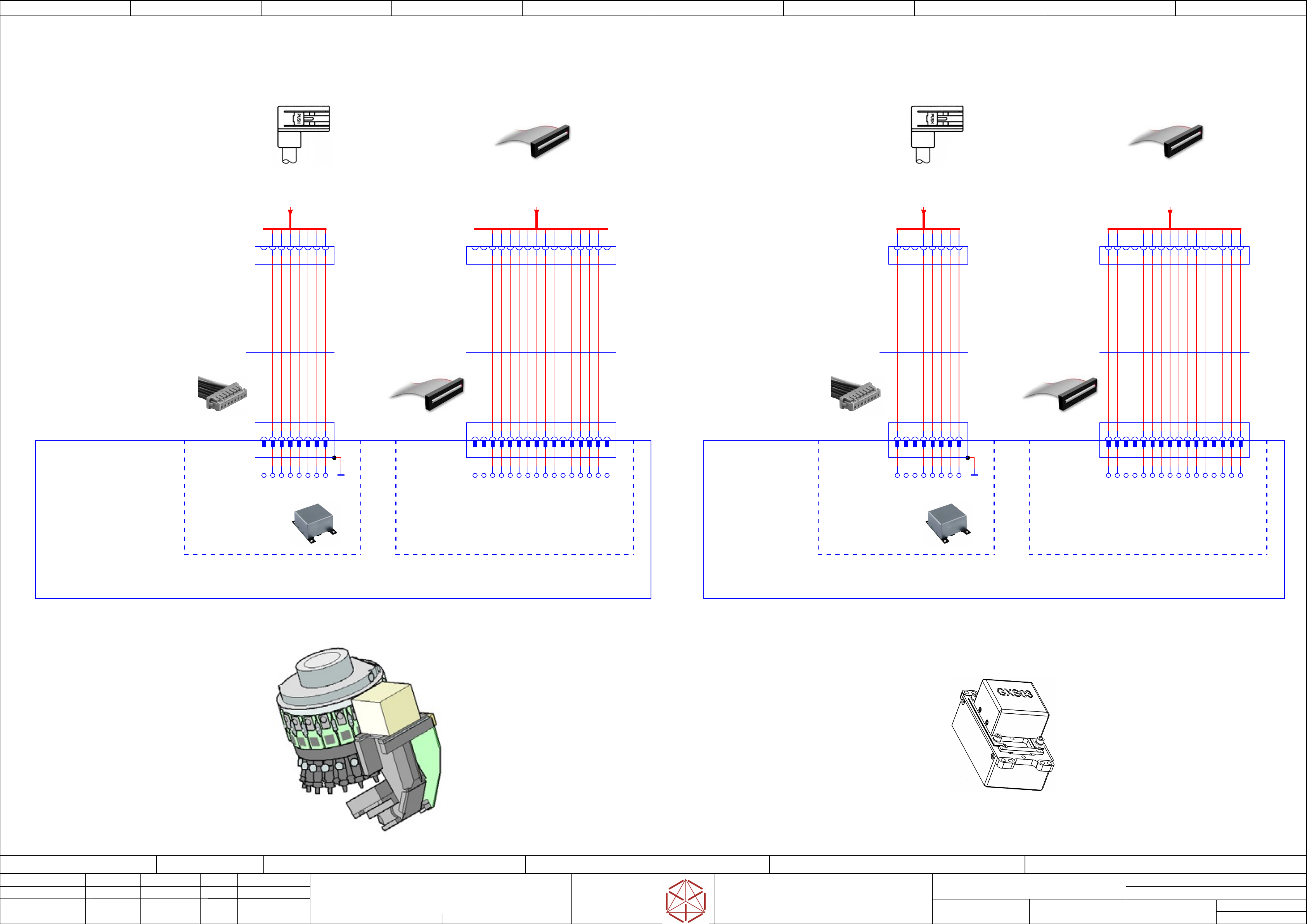
Placement-Head CP20 and
Placement-Head CP20 and
Placement-Head CP20 and
Placement-Head CP20 and
Component-Camera & PCB-Camera
Component
-Camera & PCB-Camera
Component-Camera & PCB-Camera
Component-Camera & PCB-Camera
Replaced by
Weitergabe sowie Vervielfältigung dieser Unterlage, Verwertung und
Mitteilung des Inhalts nicht gestattet, soweit nicht ausdrücklich zugestanden.
Proprietary Data, company confidential.
All rights reserved
Copying of this document, giving it to others and the use or
communication of the contents thereof, are forbidden without express authority.
Doc. No.
00 01 02 03 04 05 06 07 08 09
Privileged business information.
Do not release
Offenders are liable to payment of damages. All rights are reserved in the
event of the grant or the registration of a utility model or design.
Zuwiederhandlungen verpflichten zu Schadenersatz. Alle Rechte vorbehalten,
insbesondere für den Fall der Patenterteilung oder GM-Eintragung vorbehalten.
Page:
Function: Gantry
==GA=TX+GA1/83
drawing number:
03146940-010201LE3
Gantry 1
Gantry 1
Gantry 1
Gantry 1
GmbH & Co KG
ASM
Assembly Systems
Copyright reserved
Ed.
Original
Pingist
Date
Date
Modification
Appr
07.02.2018
Name
Size DIN A2
Sheet
83
/
5
Component
Component
Component
Component
camera (Type 23)
camer
a (Type 23)
camera (Type 23)
camera (Type 23)
6x6 GigE
6x6 GigE
6x6 GigE
6x6 GigE
Placement Head
Placement Head
Placement Head
Placement Head
SpeedStar (C&P20)
SpeedStar (C&P20)
SpeedStar (C&P20)
SpeedStar (C&P20)
PCB - Camera
PCB - Camer
a
PCB - Camera
PCB - Camera
(Type 34)
(
Type 34)
(Type 34)
(Type 34)
28 GigE
28 GigE
28 GigE
28 GigE
-X1
-
X1
-X1
-X1
1
2
3
4
5
6
7
8
9
10
11
12
13
14
15
16
GND
+42V
MCAN_RX
GND
MCAN_TX_
PORTAL-ID0
+24V
HCU-TRIG_
+42V
GND
MCAN_RX_
MCAN_TX
GND
PORTAL-ID1
HCU-TRIG
GND
1
3
5
6
4
2
7
13
9
10
11
12
14
15
16
8
1
3
5
6
2
8
7
4
1
3
5
6
4
2
7
13
9
10
11
12
14
15
16
8
1
3
5
6
2
8
7
4
Gantry 2
Placement-Head CP20 and
Component-Camera & PCB-Camera
Component camera C+P (Type 23) 6x6 GigE
Component camer
a C+P (Type 23) 6x6 GigE
Component camera C+P (Type 23) 6x6 GigE
Component camera C+P (Type 23) 6x6 GigE
PCB camera (Type 34) 28 GigE
PCB camer
a (Type 34) 28 GigE
PCB camera (Type 34) 28 GigE
PCB camera (Type 34) 28 GigE
2
4 6 81 3 5 7
-X1
-
X1
-X1
-X1
03101431
GXS03 GigE
CCD VGA camera
BAUMER
-CAM1
-CAM1
-CAM1
-CAM1
03105195
03105195
03105195
03105195
Gantry 1
Component Camera C+P
Component Camer
a C+P
Component Camera C+P
Component Camera C+P
(Type 23) 6x6 GigE
(
Type 23) 6x6 GigE
(Type 23) 6x6 GigE
(Type 23) 6x6 GigE
-Co_Cam
-Co_Cam
-Co_Cam
-Co_Cam
031178750
PCBA
Vision LED controller
VLC41 GigE
-A1
-
A1
-A1
-A1
MX1+
MX2+
MX3+
MX4+
MX1-
MX2-
MX3-
MX4-
SHIELD
-X9.VHI
-
X9.VHI
-X9.VHI
-X9.VHI
1
2
3
4
5
6
7
8
9
10
11
12
13
14
15
16
-X1.VLC
-
X1.VLC
-X1.VLC
-X1.VLC
1
2
3
4
5
6
7
8
9
10
11
12
13
14
15
16
7531 8642
-X14.VHI
-
X14.VHI
-X14.VHI
-X14.VHI
7531 8642
-X1.CAM
-
X1.CAM
-X1.CAM
-X1.CAM
510 mm
4x2x0,09
CAT5 cable
03106501
03106501
03106501
03106501
-W1
-
W1
-W1
-W1
Cable Camera Type 23 GigE
BU/WH
BU
OG
OG/WH
GN/WH
GN
BN
BN/WH
545 mm
16x0,05
Flat round cable
03106510
03106510
03106510
03106510
-W1
-
W1
-W1
-W1
Cable VHI - VLC23 GigE
1
2
3
4
5
6
7
8
9
10
11
12
13
14
15
16
-X1
-X1
-X1
-X1
1
2
3
4
5
6
7
8
9
10
11
12
13
14
15
16
GND
+42V
MCAN_RX
GND
MCAN_TX_
PORTAL-ID0
+24V
HCU-TRIG_
+42V
GND
MCAN_RX_
MCAN_TX
GND
PORTAL-ID1
HCU-TRIG
GND
-X1.VHI
-
X1.VHI
-X1.VHI
-X1.VHI
1
2
3
4
5
6
7
8
9
10
11
12
13
14
15
16
-X1.VLC
-
X1.VLC
-X1.VLC
-X1.VLC
1
2
3
4
5
6
7
8
9
10
11
12
13
14
15
16
03100758
PCBA
Vision LED controller
VLC34 GigE
-A2
-
A2
-A2
-A2
580 mm
16x0,05
Flat round cable
03097629
03097629
03097629
03097629
-W1
-
W1
-W1
-W1
Cable VHI - VLC34 GigE
1
2
3
4
5
6
7
8
9
10
11
12
13
14
15
16
03101402
03101402
03101402
03101402
Gantry 1
PCB camera
PCB camer
a
PCB camera
PCB camera
(Type 34) 28 GigE
(
Type 34) 28 GigE
(Type 34) 28 GigE
(Type 34) 28 GigE
-PCB_Cam
-PCB_Cam
-PCB_Cam
-PCB_Cam
2 4 6 81 3 5 7
-X1
-
X1
-X1
-X1
7531 8642
-X16.VHI
-
X16.VHI
-X16.VHI
-X16.VHI
7531 8642
-X1.CAM
-
X1.CAM
-X1.CAM
-X1.CAM
03101431
GXS03 GigE
CCD VGA camera
BAUMER
-CAM2
-CAM2
-CAM2
-CAM2
MX1+
MX2+
MX3+
MX4+
MX1-
MX2-
MX3-
MX4-
SHIELD
540 mm
4x2x0,09
CAT5 cable
03090967
03090967
03090967
03090967
-W1
-
W1
-W1
-W1
Cable Camera Type 34 GigE
BU/WH
BU
OG
OG/WH
GN/WH
GN
BN
BN/WH
[from Vision Head Interface]
==GA1=+-X9.VHI
-VHI-X.J9:1 /82.06
[from Vision Head Interface]
==GA1=+-X14.VHI
-VHI-X.J14:1 /82.05
[from Vision Head Interface]
==GA1=+-X1.VHI
82.09
[from Vision Head Interface]
==GA1=+-X16.VHI
82.07
electric_schematic SIPLACE TX_V2
electric_schematic SIPLACE TX_V2
electric_schematic SIPLACE TX_V2
electric_schematic SIPLACE TX_V2
90012669-010501LE3
Replaced by
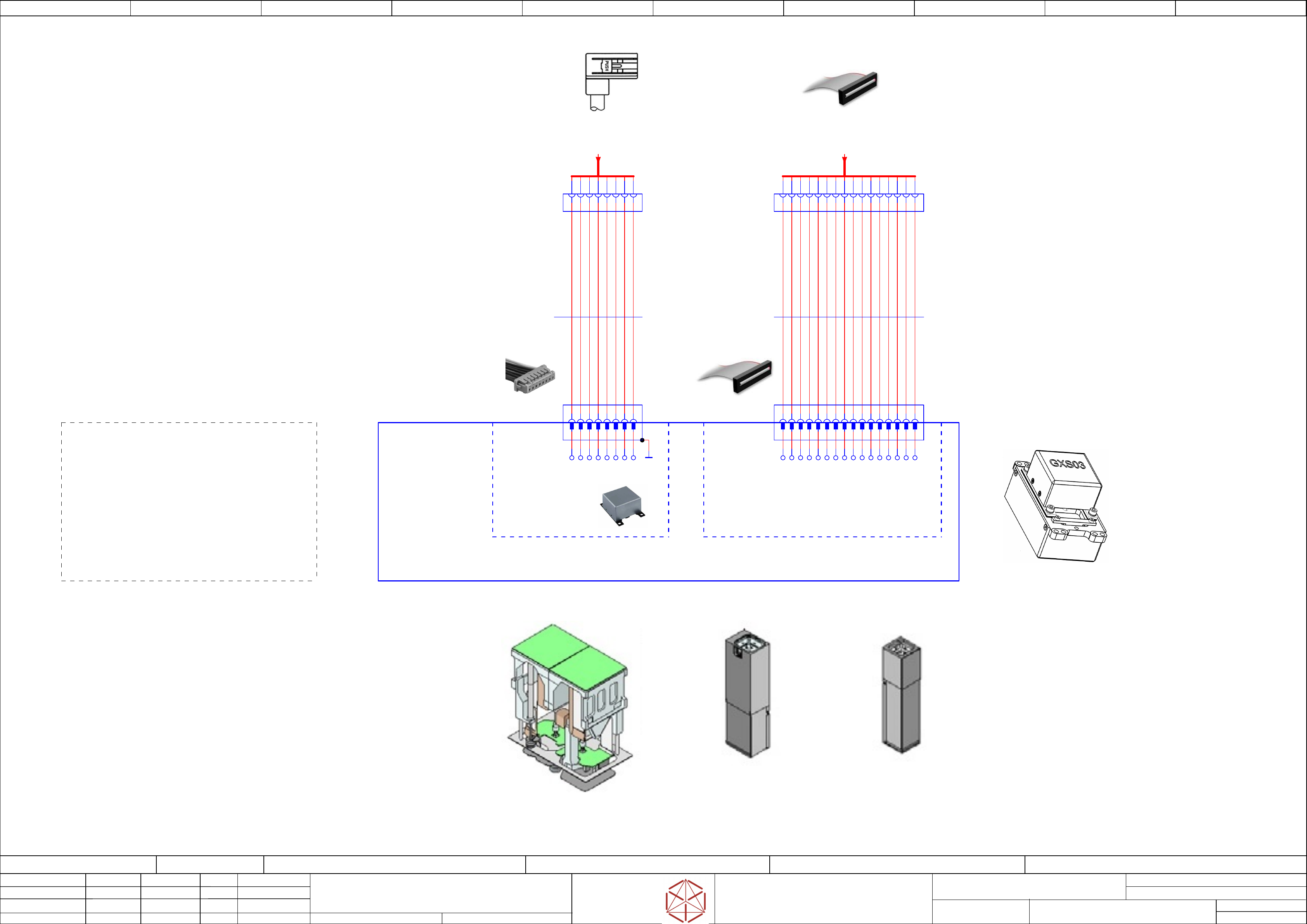
TWIN-Head & PCB-Camera
TWIN-Head & PCB-Camera
TWIN-Head & PCB-Camera
TWIN-Head & PCB-Camera
Replaced by
Weitergabe sowie Vervielfältigung dieser Unterlage, Verwertung und
Mitteilung des Inhalts nicht gestattet, soweit nicht ausdrücklich zugestanden.
Proprietary Data, company confidential.
All rights reserved
Copying of this document, giving it to others and the use or
communication of the contents thereof, are forbidden without express authority.
Doc. No.
00 01 02 03 04 05 06 07 08 09
Privileged business information.
Do not release
Offenders are liable to payment of damages. All rights are reserved in the
event of the grant or the registration of a utility model or design.
Zuwiederhandlungen verpflichten zu Schadenersatz. Alle Rechte vorbehalten,
insbesondere für den Fall der Patenterteilung oder GM-Eintragung vorbehalten.
Page:
Function: Gantry
==GA=TX+GA1/84
drawing number:
03146940-010201LE3
Gantry 1
Gantry 1
Gantry 1
Gantry 1
GmbH & Co KG
ASM
Assembly Systems
Copyright reserved
Ed.
Original
Pingist
Date
Date
Modification
Appr
07.02.2018
Name
Size DIN A2
Sheet
84
/
5
PCB - Camera
PCB - Camera
PCB - Camera
PCB - Camera
(Type 34)
(
Type 34)
(Type 34)
(Type 34)
28 GigE
28 GigE
28 GigE
28 GigE
1
3
5
6
4
2
7
13
9
10
11
12
14
15
16
8
1
3
5
6
2
8
7
4
Placement Heads
Placement Heads
Placement Heads
Placement Heads
TwinStar (TH)
T
winStar (TH)
TwinStar (TH)
TwinStar (TH)
Stationary
Stationary
Stationary
Stationary
Component camera
Component camer
a
Component camera
Component camera
(Type 25) 16x16 GigE
(
Type 25) 16x16 GigE
(Type 25) 16x16 GigE
(Type 25) 16x16 GigE
(Flip-Chip Kamera)
(Fl
ip-Chip Kamera)
(Flip-Chip Kamera)
(Flip-Chip Kamera)
Stationary
Stationary
Stationary
Stationary
Component camera
Component camer
a
Component camera
Component camera
(Type 33) 55x45 GigE
(
Type 33) 55x45 GigE
(Type 33) 55x45 GigE
(Type 33) 55x45 GigE
(Fine-pitch camera)
(Fine-pi
tch camera)
(Fine-pitch camera)
(Fine-pitch camera)
+
+
+
+
OR
OR
OR
OR
Gantry 1
Twin-Head and PCB-Camera
PCB camera (Type 34) 28 GigE
PCB camer
a (Type 34) 28 GigE
PCB camera (Type 34) 28 GigE
PCB camera (Type 34) 28 GigE
Note:
Note:
Note:
Note:
No component camera installed.
No component camer
a installed.
No component camera installed.
No component camera installed.
-X1
-
X1
-X1
-X1
1
2
3
4
5
6
7
8
9
10
11
12
13
14
15
16
GND
+42V
MCAN_RX
GND
MCAN_TX_
PORTAL-ID0
+24V
HCU-TRIG_
+42V
GND
MCAN_RX_
MCAN_TX
GND
PORTAL-ID1
HCU-TRIG
GND
-X1.VHI
-X1.VHI
-X1.VHI
-X1.VHI
1
2
3
4
5
6
7
8
9
10
11
12
13
14
15
16
-X1.VLC
-
X1.VLC
-X1.VLC
-X1.VLC
1
2
3
4
5
6
7
8
9
10
11
12
13
14
15
16
03100758
PCBA
Vision LED controller
VLC34 GigE
-A2
-
A2
-A2
-A2
580 mm
16x0,05
Flat round cable
03097629
03097629
03097629
03097629
-W1
-
W1
-W1
-W1
Cable VHI - VLC34 GigE
1
2
3
4
5
6
7
8
9
10
11
12
13
14
15
16
03101402
03101402
03101402
03101402
Gantry 1
PCB camera
PCB camer
a
PCB camera
PCB camera
(Type 34) 28 GigE
(
Type 34) 28 GigE
(Type 34) 28 GigE
(Type 34) 28 GigE
-PCB_Cam
-PCB_Cam
-PCB_Cam
-PCB_Cam
2 4 6 81 3 5 7
-X1
-
X1
-X1
-X1
7531 8642
-X16.VHI
-X16.VHI
-X16.VHI
-X16.VHI
7531 8642
-X1.CAM
-
X1.CAM
-X1.CAM
-X1.CAM
03101431
GXS03 GigE
CCD VGA camera
BAUMER
-CAM2
-CAM2
-CAM2
-CAM2
MX1+
MX2+
MX3+
MX4+
MX1-
MX2-
MX3-
MX4-
SHIELD
540 mm
4x2x0,09
CAT5 cable
03090967
03090967
03090967
03090967
-W1
-
W1
-W1
-W1
Cable Camera Type 34 GigE
BU/WH
BU
OG
OG/WH
GN/WH
GN
BN
BN/WH
[from Vision Head Interface]
==GA1=+-X1.VHI
82.09
[from Vision Head Interface]
==GA1=+-X16.VHI
82.07
electric_schematic SIPLACE TX_V2
electric_schematic SIPLACE TX_V2
electric_schematic SIPLACE TX_V2
electric_schematic SIPLACE TX_V2
90012669-010501LE3
Replaced by
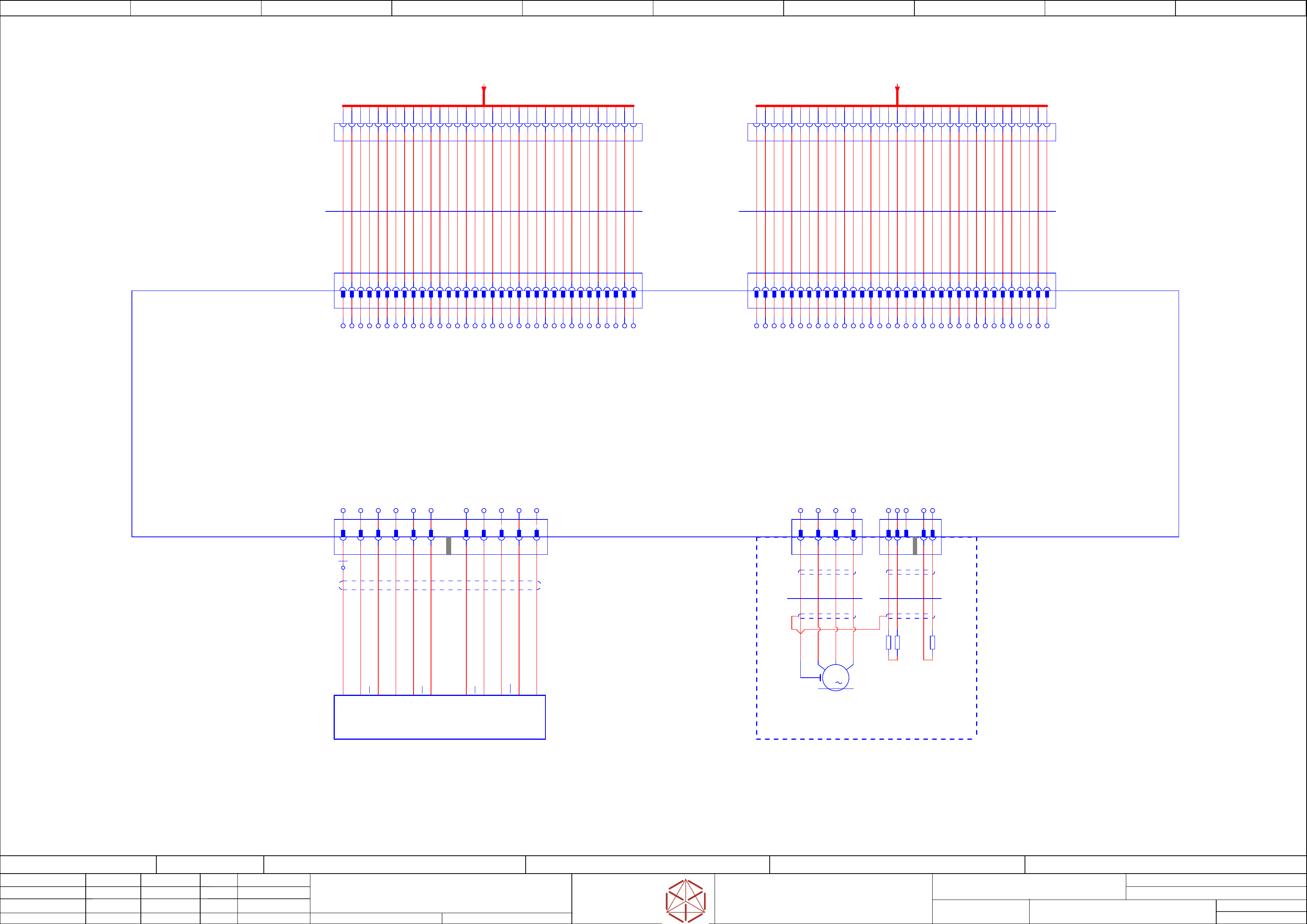
Motor-Y
Motor-Y
Motor-Y
Motor-Y
Replaced by
Weitergabe sowie Vervielfältigung dieser Unterlage, Verwertung und
Mitteilung des Inhalts nicht gestattet, soweit nicht ausdrücklich zugestanden.
Proprietary Data, company confidential.
All rights reserved
Copying of this document, giving it to others and the use or
communication of the contents thereof, are forbidden without express authority.
Doc. No.
00 01 02 03 04 05 06 07 08 09
Privileged business information.
Do not release
Offenders are liable to payment of damages. All rights are reserved in the
event of the grant or the registration of a utility model or design.
Zuwiederhandlungen verpflichten zu Schadenersatz. Alle Rechte vorbehalten,
insbesondere für den Fall der Patenterteilung oder GM-Eintragung vorbehalten.
Page:
Function: Gantry
==GA=TX+GA2/85
drawing number:
03146940-010201LE3
Gantry 2
Gantry 2
Gantry 2
Gantry 2
GmbH & Co KG
ASM
Assembly Systems
Copyright reserved
Ed.
Original
Pingist
Date
Langer D.
Date
Modification
Appr
07.02.2018
Name
Size DIN A2
Sheet
85
/
4
-X1
-
X1
-X1
-X1
Trailing cable
T
railing cable
Trailing cable
Trailing cable
Y motor
Y motor
Y motor
Y motor
1
2
3
4
5
6
7
8
9
10
11
12
13
14
15
16
17
18
19
20
21
22
23
24
27
25
26
28
29
30
31
32
33
34
-X2
-
X2
-X2
-X2
Trailing cable
T
railing cable
Trailing cable
Trailing cable
Y motor
Y motor
Y motor
Y motor
1
2
3
4
5
6
7
8
9
10
11
12
13
14
15
16
17
18
19
20
21
22
23
24
27
25
26
28
29
30
31
32
33
34
Gantry 2
KEY
22
KEY
2
4
6
8
10
12
14
16
18
20
22
24
26
28
30
32
3
5
7
9
11
13
15
19
21
23
25
27
29
31
33
1
34
17
2
4
6
8
10
12
14
16
18
20
22
24
26
28
30
32
3
5
7
9
11
13
15
19
21
23
25
27
29
31
33
1
34
17
-X1.GI
-
X1.GI
-X1.GI
-X1.GI
1
2
3
4
5
6
7
8
9
10
11
12
13
14
15
16
17
18
19
20
21
22
23
24
26
28
29
30
31
33
25
27
32
34
-X1.TI
-
X1.TI
-X1.TI
-X1.TI
1
2
3
4
5
6
7
8
9
10
11
12
13
14
15
16
17
18
19
20
21
22
23
24
26
28
29
30
31
33
25
27
32
34
-X2.GI
-
X2.GI
-X2.GI
-X2.GI
1
2
3
4
5
6
7
8
9
10
11
12
13
14
15
16
17
18
19
20
21
22
23
24
26
28
29
30
31
33
25
27
32
34
-X2.TI
-
X2.TI
-X2.TI
-X2.TI
1
2
3
4
5
6
7
8
9
10
11
12
13
14
15
16
17
18
19
20
21
22
23
24
26
28
29
30
31
33
25
27
32
34
-GI
-GI
-GI
-GI
Gantry 2
Gantry interface 2 TX V2
Gantry interf
ace 2 TX V2
Gantry interface 2 TX V2
Gantry interface 2 TX V2
03138255
1 2 3 4 5 6 8 9 1110 12
Encoder signals Yaxis
Encoder signals Y
axis
Encoder signals Yaxis
Encoder signals Yaxis
-X11
-
X11
-X11
-X11
SCREEN
YMOTORU
YMOTORU
YMOTORU
YMOTORV
YMOTORV
YMOTORV
YMOTORW
YMOTORW
YMOTORW
SCREEN
YTEMPSENS
YTRACKNN/FDB_EPM_CH8_BUS_N
GND_FELV
YTRACKB/FDB_EPM_CH6_BUS_P
YTRACKAN/FDB_EPM_CH5_BUS_N
GND_FELV
SCREEN
YMOTORU
YMOTORU
YMOTORU
YMOTORV
YMOTORV
YMOTORV
YMOTORW
YMOTORW
YMOTORW
SCREEN
GND_FELV
YTRACKN/FDB_EPM_CH8_BUS_P
YTRACKBN/FDB_EPM_CH6_BUS_N
GND_FELV
YTRACKA/FDB_EPM_CH5_BUS_P
SCREEN
SCREEN
YMOTORU
YMOTORU
YMOTORU
YMOTORV
YMOTORV
YMOTORV
YMOTORW
YMOTORW
YMOTORW
SCREEN
Y_AXIS_ERROR_24V_N
GND_FELV
P24V_BUFF1
GND_FELV
GND_FELV
P24V_BUFF1
SCREEN
YMOTORU
YMOTORU
YMOTORU
YMOTORV
YMOTORV
YMOTORV
YMOTORW
YMOTORW
YMOTORW
SCREEN
P24V_BUFF1
GND_FELV
GND_FELV
P24V_BUFF1
GND_FELV
SCREEN
SCREEN
YTRACKA/FDB_EPM_CH5_BUS_P
YTRACKAN/FDB_EPM_CH5_BUS_N
GND_FELV
YTRACKB/FDB_EPM_CH6_BUS_P
YTRACKBN/FDB_EPM_CH6_BUS_N
YTRACKN/FDB_EPM_CH8_BUS_P
YTRACKNN/FDB_EPM_CH8_BUS_N
P5V
Y_ERROR5V
NC
7
-X11.GI
-
X11.GI
-X11.GI
-X11.GI
1 2 3 4 5 6 8 9 11 12
T1 YE
GND WH
T2 PK
Drain wire
T2 RD
+5V BK
US BU
RI BN
Test TR (transp.)
RI GY
T1 GN
03094996
Scanning head MS 22.84, Y axis (1020mm)
S
canning head MS 22.84, Y axis (1020mm)
Scanning head MS 22.84, Y axis (1020mm)
Scanning head MS 22.84, Y axis (1020mm)
Gantry 2
-UY2
-UY2
-UY2
-UY2
10
SCREEN
Drain wire
WH/GN
WH/GN
WH/GN
WH/GN
1 2 3 4
-X12
-
X12
-X12
-X12
Y axis
Y axis
Y axis
Y axis
Power_Y-Motor
P
ower_Y-Motor
Power_Y-Motor
Power_Y-Motor
SCREEN
Y Motor_U
Y Motor_V
Y Motor_W
1 2 3
-X13
-
X13
-X13
-X13
Y axis
Y axis
Y axis
Y axis
Temp. sensor PTC
T
emp. sensor PTC
Temp. sensor PTC
Temp. sensor PTC
GND_FELV
PTC_Y-Motor
NC
PT100_Test-Pin
PT100_Test-Pin
5 6
4
Phase C
Phase B
Phase A
GND
3
M
4
KEY
740 mm
4xAWG18
Power
-W1
WH
GN
BK
RD
SH
SH
-SNM115.1
Temp
Sens
PHASE C3
-PT100
not used
-
+
BN
820 mm
4xAWG24
Temp
-W2
WH
GN
YE
-X3
-X3
-X3
-X3
1 2 3 4
-X4
-
X4
-X4
-X4
1 2 5 6
SH
SH
03095097
Linear motor primary Y axis
Linear motor primary Y axis
Linear motor primary Y axis
Linear motor primary Y axis
Gantry 2
-MY2
-MY2
-MY2
-MY2
1485 mm
34x0,14
Flat cable
03147221
03147221
03147221
03147221
-W1
-
W1
-W1
-W1
1
2
3
4
5
6
7
8
9
10
11
12
13
14
15
16
17
18
19
20
21
-SNM115.2
Temp
Sens
PHASE A2
23
24
25
26
27
28
29
30
31
32
33
34
1490 mm
34x0,14
Flat cable
03147222
03147222
03147222
03147222
-W2
-
W2
-W2
-W2
1
2
3
4
5
6
7
8
9
10
11
12
13
14
15
16
17
18
19
20
21
22
23
24
25
26
27
28
29
30
31
32
33
34
[Trailing interface]
==GA2+-X1.TI2
==CH+GA-TI2-X1:1 ==CH+GA/63.01
[Trailing interface]
==GA2+-X2.TI2
==CH+GA-TI2-X2:1 ==CH+GA/63.05
7
KEY