KE2040Instruction Manual Ver2.01,REV04.2003.6.25.pdf - 第244页
4 – 134 (3-2) Coher ence check item s: er ror conditions Data ty pe Item Error conditions Any centering method w hich allows placement is not set. Centering method The st andard VCS and optional VCS are not available for…
4 – 133
Data type Item Error conditions
Placement
data
Placement layer
(for a KE-2030)
When the “Sequential and Mix Mode” is selected at the menu
item “2030 Mode Specification” on the “2000 Option” tab, and
“Use manual station/position arrangements” as the menu item
“Pick Data” of the “Assignments” tab of the “Optimization”
menu, and all component pick-up positions are specified, an
error occurs if the In and OUT stations are not specified in
this order as the layer assignment order of the IN station and
OUT station on Placement data respectively.
* When the component placement head is automatically set,
the machine obtains information on the specified station
from Pick data.
If both of the stations have the specified component
placement heads, those heads pass the layer check.
Maximum PL value on the IN side ≦Minimum simultaneous
placement PL value ≦Maximum simultaneous placement PL
value ≦Minimum PL value on the OUT side
PL: placement layer number
4 – 134
(3-2) Coherence check items: error conditions
Data type Item Error conditions
Any centering method which allows placement is not set. Centering method
The standard VCS and optional VCS are not available for
vision centering.
Component package
Although the “Packaging style” is set in Component data of
tray components, the item “Packaging style” cannot be set to
“Tray”.
If the “Parallel Mode” is selected at the menu item “2030
Mode Specification” of the “2000 Option” tab, “Use permanent
nozzle setup from MSL Setup” is selected at the menu item
“Nozzle” of the “Assignments” tab of the “Optimization” menu,
and a nozzle specified on the Component data screen does
not exist on both of the stations.
If the “Parallel Mode” is selected at the menu item “2030
Mode Specification” of the “2000 Option” tab, “Auto arrange
empty nozzle positions” is selected at the menu item “Nozzle”
of the “Assignments” tab of the “Optimization” menu, a nozzle
specified on the Component data screen does not exist on
both of the stations, and there is no not-occupied ATC
position.
If the “Sequential and Mix Mode” is selected at the menu item
“2030 Mode Specification” of the “2000 Option” tab, “Use
permanent nozzle setup from MSL Setup” is selected at the
menu item “Nozzle” of the “Assignments” tab of the
“Optimization” menu, “AUTO” is selected at the menu item
“SPLY” (supply) of any component on the Pick data screen
that is associated with Component data, and a nozzle
specified on the Component data screen does not exist on
both of the stations.
Nozzle (for a KE-2030)
If the “Sequential and Mix Mode” is selected at the menu item
“2030 Mode Specification” of the “2000 Option” tab, “Auto
arrange empty nozzle positions” is selected at the menu item
“Nozzle” of the “Assignments” tab of the “Optimization” menu,
“AUTO” is selected at the menu item “SPLY” (supply) of any
component on the Pick data screen that is associated with
Component data, and a nozzle specified on the Component
data screen does not exist on both of the stations.
Component
data
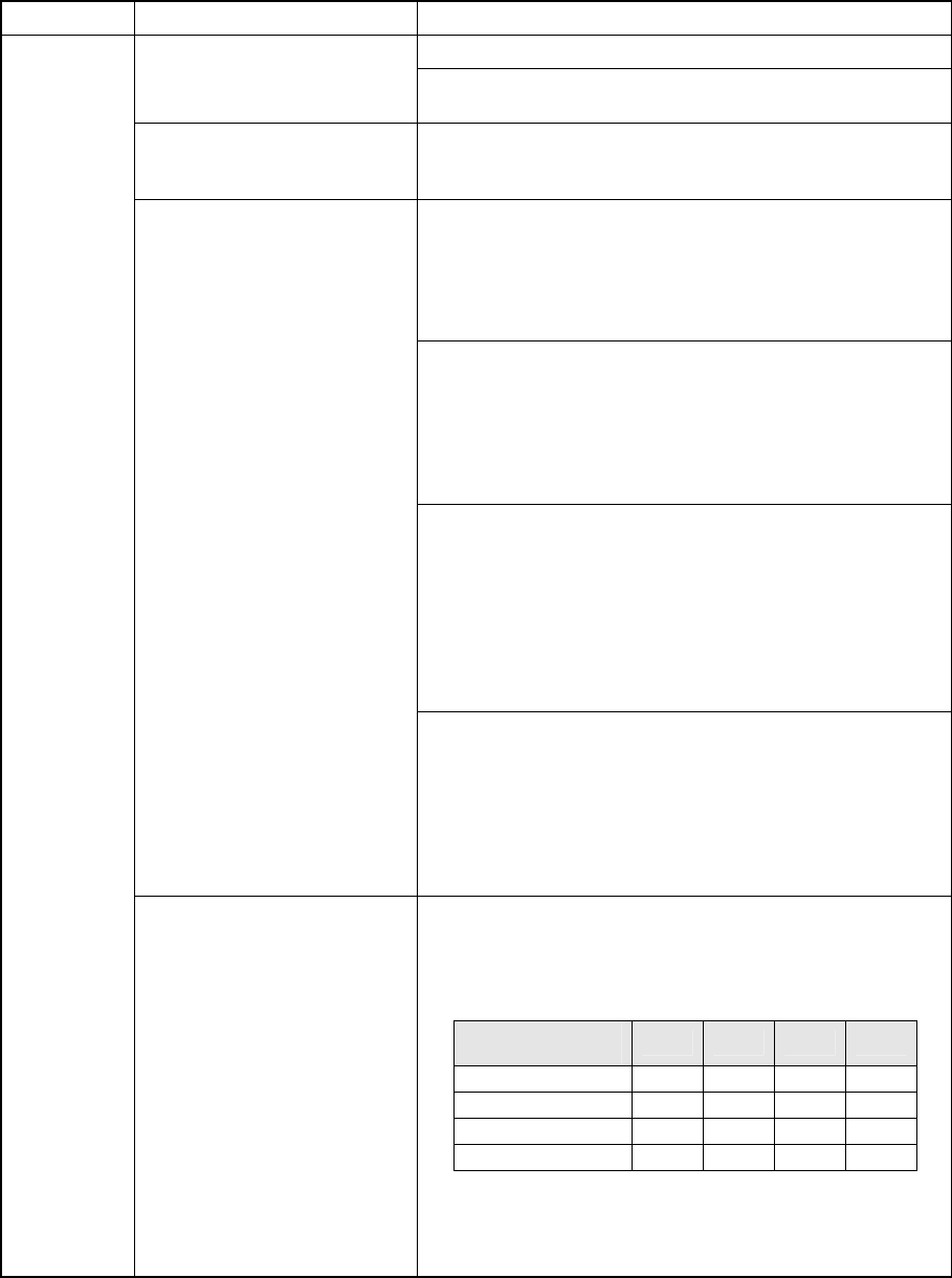
Component dimensions
The dimensions set in Component data cannot be handled
with the machine.
<Error conditions>
Note: △ means that the indicated component height is
applicable if the component height is set to "20 mm"
on the MS Parameter menu of a chip
shooter/mounter.
Component
height
2010 2020 2030 2040
0 < H ≦ 6 mm ○ ○ ○ ○
6 < H ≦ 12 mm △ ○ ○
12 < H ≦ 20 mm △ △ ○
20 < H ≦ 25 mm ○
4 – 135
Data type Item Error conditions
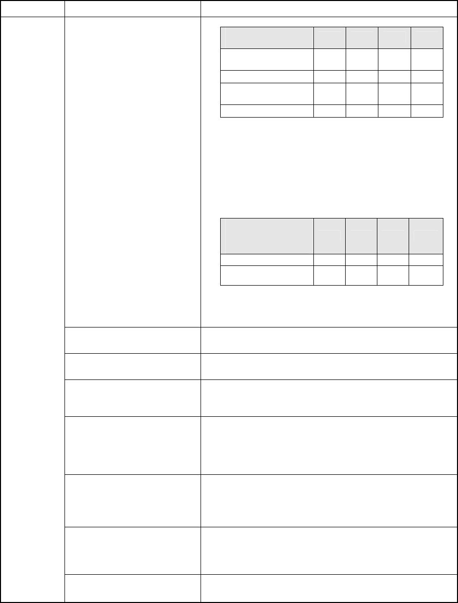
Component dimensions
Note:
△
means that the indicated dimensions are applicable
if an image of a component such as a connector is
divided, then recognized. The maximum dimensions
of a component is 150 mm (150 x 50). When you do
not use he FMLA head of a KE-2020, the maximum
dimensions are 29 mm.
If the machine does not use the KE-2020 MNLA
head, the minimum dimension is 0.45 mm or less.
Note: When you do not use the FMLA head of a KE-2020,
the maximum length of a diagonal line becomes 30.7
mm or less.
Chip rise detecting option
There is not any station that can handle a chip rise detection
unit.
Head (when vision centering)
All of the FMLA heads (R head for a KE-2020, L and R heads
for a KE-2040) are set to “Not used” on the Setup menu.
Head (when laser centering)
All of the NMLA heads/FMLA heads are set to “Not used” on
the Setup menu, and those heads are set to “Used” on the
Component data editing screen.
Head
(0603 component)
Although all the MNLA heads are set to “Not used” and the
vision centering function is not selected, there is a component
whose thickness is thinner than 0.3 mm or whose minimum
outer dimension is less than 0.45 mm (for example, a 0603
component).
Nozzle data (“Grip Position”
and “Nozzle Direction at
Picking”)
- A value other than “0” is set to the X” field of the menu item
“Grip Position.”
- A value other than 0, 90, 180 and 270 degrees is set at the
menu item “Nozzle Direction at Picking.”
Shuttle
(Expansion – MTC/MTS/DTS)
The “Packaging style” is set to “Tray”, “Feeder” is set to
“MTC/MTS”, “Compo Reject to” is set to “Tray Restore”,
“Shuttle” is set to “Mecha”, and there is only an MTC(s) in the
line.
Component
data
Prerotate angle
(When laser-centering)
The prerotate angle (A) is not set to a value within the
regulated range: 0 degree ≦ A < 45 degrees.
Component
dimensions
2010 2020 2030 2040
L < 0.45 mm ○
○
Note
○
0.45 ≦ L ≦ 26.5mm ○ ○ ○ ○
26.5 < L ≦ 50 mm
○
Note
○
50 < L ≦ 150 mm △ △
The length of a
diagonal line of a
component to be
centered with laser
2010 2020 2030 2040
30.7 mm or less ○ ○ ○ ○
30.7 mm to 47 mm
○
Note
○