KE2040Instruction Manual Ver2.01,REV04.2003.6.25.pdf - 第250页
4 – 140 (3-4) Coher ence check item s: er ror conditions Data ty pe Item Error conditions Placement of vision components (over 0.4 mm) (Lead components) The st andard VCS or optional VCS (37.5 mm, 27 mm or 18 mm) is not …
4 – 139
Data type Item Error conditions
The system cannot handle a bulk feeder type (BF25RS,
BF25CS, BF28RS or BF28CS).
Bulk feeder type (BF25RS,
BF25CS, BF28RS, BF28CS)
There is no available bulk feeder (BF25RS, BF25CS,
BF28RS, BF28CS) when “Auto” is selected in Pick data on a
component, which is to use a bulk feeder.
Placement of an SOT
component whose direction is
checked
(2000 series only)
If an SOT direction-checking table cannot be used in the
placement data of an SOT component whose direction is
checked.
– An IC recovery belt is not installed although the setting
item “Compo Reject to” of a component is set to “Trash
conveyor” and “Auto” is selected as a station in Pick data.
– An IC recovery belt is not installed although the setting
item “Compo Reject to” of a component to be picked up is
set to “Trash conveyor”.
Component Discarding
– The tray feeder (see Note) that is associated with the
component discarding destination is not installed although
the setting item “Compo Reject to” of a component to be
picked up is set to “Tray restore”, and “Auto” is selected as
a station in Pick data.
– The tray feeder (see Note) associated with the component
discarding destination is not installed although the setting
item “Compo Reject to” of a component to be picked up is
set to “Tray restore”.
– A station is set to an MTC when the setting item “Compo
Reject to” of a component is set to “Tray restore” and the
setting item “Shuttle” is set to “Mecha”.
Note: Tray feeders associated with the setting “Tray restore”
are as follows:
– MTC: TR6S, TR6D and TR4S
– MTS: TR5S and TR5D
– Tray holder: all types of tray holders
– DTS
Overlapped with a DTS If the area occupied by a specified feeder is overlapped with
that by a DTS.
If the “Sequential and Mix Mode” is selected at the menu item
“2030 Mode Specification” of the “2000 Option” tab, “Use
permanent nozzle setup from MSL Setup” is selected at the
menu item “Nozzle” of the “Assignments” tab of the
“Optimization” menu, the menu item “SPLY” (supply) is all
entered to the pick data on the same component on the Pick
data screen that is associated with Component data, and a
nozzle specified on the Component data screen does not
exist on both of the stations.
Note that if a nozzle is located at either of both stations when
Pick data is set to both stations, the system will not handle
this situation as an error.
Nozzle (for a KE-2030)
If the “Sequential and Mix Mode” is selected at the menu item
“2030 Mode Specification” of the “2000 Option” tab, “Auto
arrange empty nozzle positions” is selected at the menu item
“Nozzle” of the “Assignments” tab of the “Optimization” menu,
the menu item “SPLY” (supply) is all entered to the pick data
on the same component on the Pick data screen that is
associated with Component data, and a nozzle specified on
the Component data screen does not exist on both of the
stations.
Note that if a nozzle is located at either of both stations when
Pick data is set to both stations, the system will not handle
this situation as an error.

4 – 140
(3-4) Coherence check items: error conditions
Data type Item Error conditions
Placement of vision
components (over 0.4 mm)
(Lead components)
The standard VCS or optional VCS (37.5 mm, 27 mm or 18
mm) is not set in Placement data of vision components
whose size is 0.4 mm or larger.
Placement of vision
components (0.3 <= Pitch < 0.4
mm) (Lead components)
The optional VCS (37.5 mm, 27 mm or 18 mm) is not set in
Placement data of vision components whose pitch is 0.3 mm
or wider, but narrower than 0.4 mm.
Placement of vision
components (0.2 <= Pitch < 0.3
mm) (Lead components)
The optional VCS (27 mm or 18 mm) is not set in Placement
data of vision components whose pitch is 0.2 mm or wider,
but narrower than 0.3 mm.
Placement of vision
components (0.135 <= Pitch <
0.2 mm) (Lead components)
The optional 18 mm VCS is not set in Placement data of
vision components whose pitch is 0.135 mm or wider, but
narrower than 0.2 mm.
Division recognition of an
extended-lead connector
If split (division) recognition is selected at the control data
menu item of an extended-lead connector (only batch
recognition is available).
Placement of general vision
components (15 < the smallest
pitch <= 22 mm) (Lead
components)
The standard VCS is not set in Placement data of general
vision components whose minimum pitch is wider than 15
mm, but 22 mm or narrower.
Placement of general vision
components (11 < the smallest
pitch <=15 mm) (Lead
components)
The standard VCS or optional 37.5 mm VCS is not set in
Placement data of general vision components whose
minimum pitch is wider than 11 mm, but 15 mm or narrower.
Placement of general vision
components (6.5 < the smallest
pitch <= 11 mm) (Lead
components)
The standard VCS or optional 37.5 mm or 27 mm VCS is not
set in Placement data of general vision components whose
minimum pitch is wider than 6.5 mm, but 11 mm or narrower.
Placement of general vision
components (0.5 <= the
smallest pitch <=6.5 mm)
(Lead components)
The standard VCS or optional 37.5 mm, 27 mm or 18 mm
VCS is not set in Placement data of general vision
components whose minimum pitch is 0.5 mm or wider, but
6.5 mm or narrower.
Placement of general vision
components (0.4 <= the
smallest pitch <0.5 mm) (Lead
components)
The optional 37.5 mm, 27 mm or 18 mm VCS is not set in
Placement data of general vision components whose
minimum pitch is 0.4 mm or wider, but narrower than 0.5 mm.
Placement of general vision
components (0.3 <= the
smallest pitch < 0.3 mm) (Lead
components)
The optional 27 mm or 18 mm VCS is not set in Placement
data of general vision components whose minimum pitch is
0.3 mm or wider, but narrower than 0.4 mm.
Placement of general vision
components (0.2 <= the
smallest pitch < 0.3 mm) (Lead
components)
The optional 18 mm VCS is not set in Placement data of
general vision components whose minimum pitch is 0.2 mm
or wider, but narrower than 0.3 mm.
Placement of vision
components (15 < the smallest
pitch <= 22 mm) (Ball
components)
The standard VCS is not set in Placement data of vision
components whose minimum pitch is wider than 15 mm, but
22 mm or narrower.
Placement of vision
components (11 < the smallest
pitch <15 mm) (Ball
components)
The standard VCS or optional 37.5 mm VCS is not set in
Placement data of vision components whose minimum pitch
is wider than 11 mm, but 15 mm or narrower.
Placement of vision
components (6.5 < the smallest
pitch <= 11 mm) (Ball
components)
The standard VCS or optional 37.5 mm or 27 mm VCS is not
set in Placement data of vision components whose minimum
pitch is wider than 6.5 mm, but 11 mm or narrower.
Vision data
Placement of vision
components (1.0 <= the
smallest pitch < 6.5 mm) (Ball
components)
The standard VCS optional 37.5 mm, 27 mm or 18 mm VCS
is not set in Placement data of vision components whose
minimum pitch is wider than 1.0 mm, but 6.5 mm or narrower.
4 – 141
Data type Item Error conditions
Placement of vision
components (0.8 <= the
smallest pitch < 1.0 mm) (Ball
components)
The optional 37.5 mm, 27 mm or 18 mm VCS is not set in
Placement data of vision components whose minimum pitch
is 0.8 mm or wider, but narrower than 1.0 mm.
Placement of vision
components (0.5 <= the
smallest pitch < 0.8 mm) (Ball
components)
The optional 27 mm or 18 mm VCS is not set in Placement
data of vision components whose minimum pitch is 0.5 mm or
wider, but narrower than 0.8 mm.
Placement of vision
components (0.35 <= the
smallest pitch < 0.5 mm) (Ball
components)
The optional 18 mm VCS is not set in Placement data of
vision components whose minimum pitch is 0.35 mm or
wider, but narrower than 0.5 mm.
The BGA vision recognition function cannot be used with the
station in Pick data of all balls or all lands vision recognition
components.
If the pitch width is equal to the pith length in the pick data on
vision all ball or all land recognition components (for a BGA
component, the width and length are 2.00 mm or longer and
for an FBGA component, they are 1.00 mm or longer), and
one of the standard type BGA, peripheral type BGA and user
ball pattern is selected as a ball pattern, but there is no
KE-2000 series station.
Pick-up of all balls or all lands
vision recognition components
If the pitch width is not equal to the pitch length and there is
no KE-2000 series station.
Number of all balls or all lands
vision recognition ball pattern
components
The number of user-defined ball pattern components in Pick
data is found to exceed 10 with the all balls or all lands vision
recognition function.
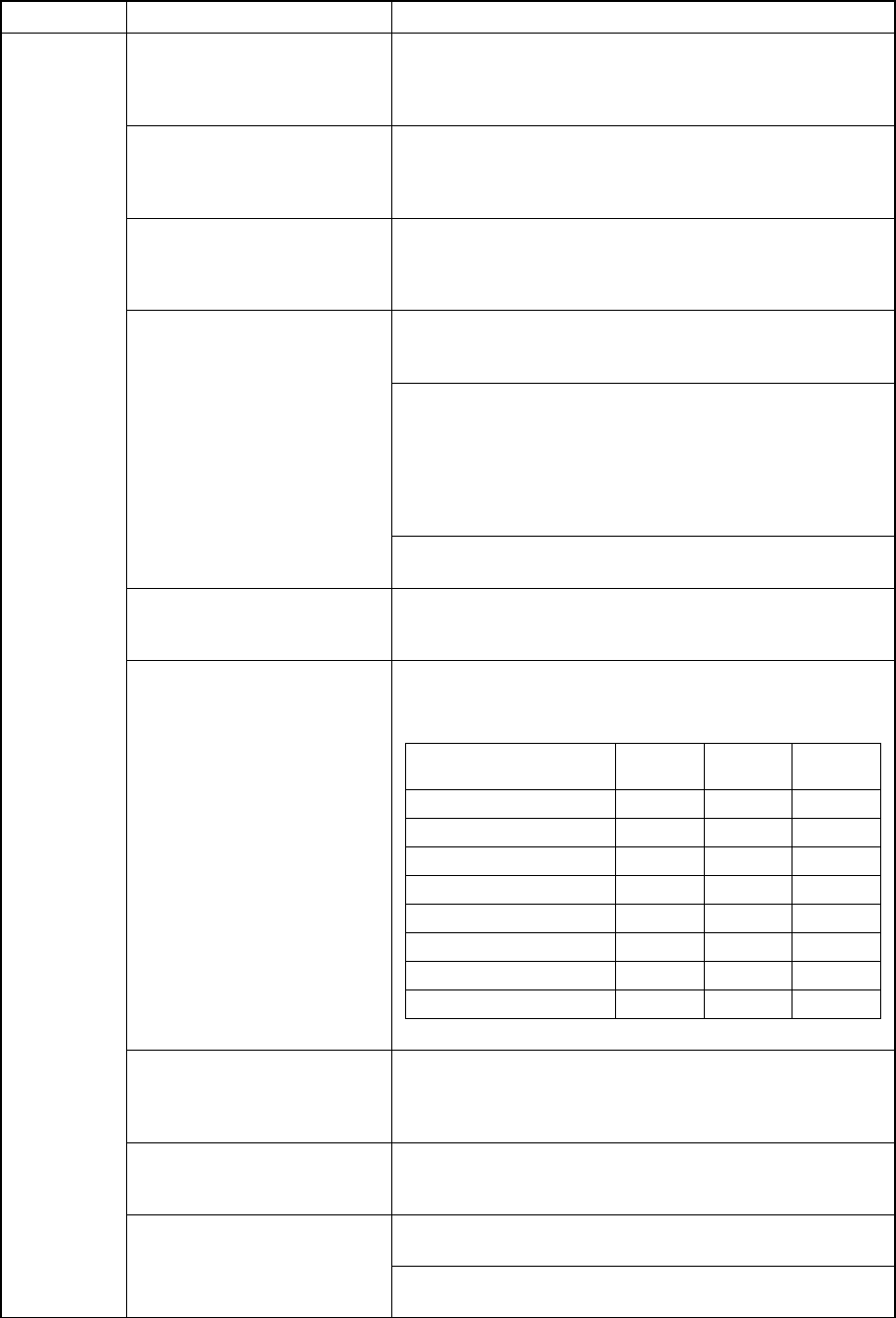
Error conditions of the VCS recognition type specified on the
MSL setup menu and the light type specified in Light data
VCS recognition type
Reflective
light
Penetra-
tive light
Side light
No recognition × × ×
BGA vision recognition × × ○
Penetrative recognition × ○ ×
Reflective recognition ○ × ×
BGA, penetrative × ○ ○
BGA, reflective ○ × ○
Penetrative, reflective ○ ○ ×
BGA, Penetrative, reflective ○ ○ ○
Light type
Component for which you can
select “Vision centering
component” as its component
type
The component size is smaller than 0.6 mm.
For components that undergo
coplanarity inspection (2000
series only)
The longer side of the component size exceeds 50 mm and
the height of the component exceeds 8.00 mm.
The “standard measurement mode” is selected and the
longer side of the component size exceeds 100 mm.
Coplanarity measurement
mode
The “high-accuracy measurement mode” is selected and the
longer side of the component exceeds 50 mm.