KE2040Instruction Manual Ver2.01,REV04.2003.6.25.pdf - 第26页
1 − 9 1.1.3 Sy stem configurat ion Color liquid-crystal display (LCD) Key boa rd Track b all FDD HDD 100 Base /10 Base Ethernet bo ard T Rear s ide op erat ion unit Area se nso r Si gnal t ower Em ergen c y st op but ton…
1 − 8
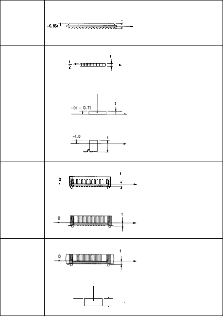
Component type Measurement position Laser height (mm)
BGA
FBGA
-0.86t
Network resistor
Same as that of the
square chip
Trimmer
- (t – 0.7)
Unidirectional
lead connector
2-way lead
connector Z-lead
connector
-1.0
J-lead socket
0
Gull-wing socket
0
Socket with
bumper
0
Other
components
-0.5t
Measurement
position with
laser
Component height
Molding
Component height
Measurement position
with laser
Measurement position
with laser
Component height
Measurement position
with laser
Component height
-0.5t
t
Component height
Component height
Component height
Measurement
position with
laser
Measurement
position with
laser
Measurement
position with
laser
Component height
Measurement
position with laser
Molding
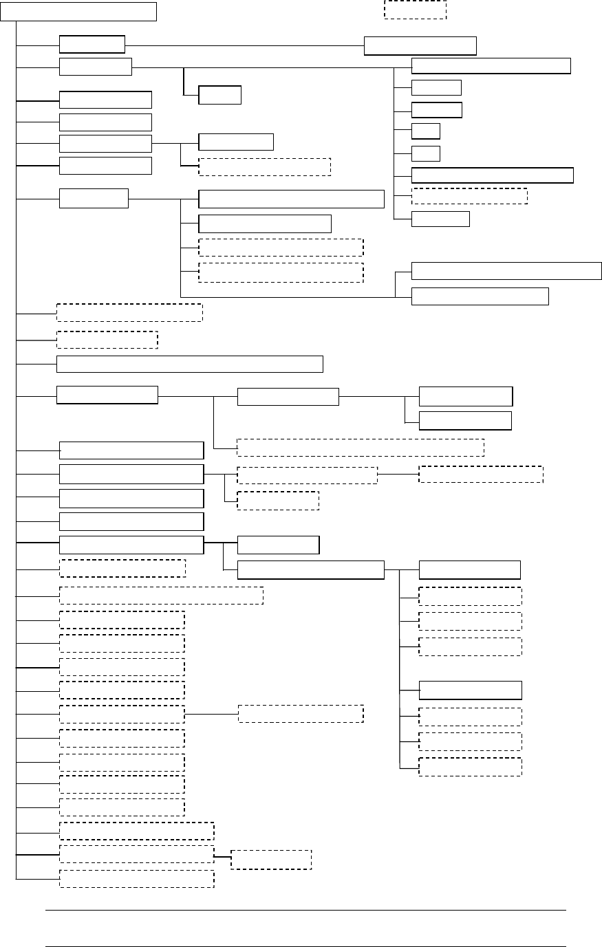
1 − 9
1.1.3 System configuration
Color liquid-crystal display (LCD)
Keyboard
Track ball
FDD
HDD
100 Base/10 Base Ethernet board T
Rear side operation unit
Area sensor
Signal tower
Emergency stop button
Placing head
Automatic tool changer (ATC)
Feeder float detecting function
Pneumatic piping system
Vision Centering System (VCS)
Batch feeder change function
Feeder bank driver
Verification function
Vision monitor
Feeder table
PWB conveyor unit
Placement station L
Automatic PWB transportation width adjustment device
Feeder position indicator function
Automatic tape cutter
Tape feeder
Stick feeder
Stack stick feeder
Non-stop operation function
Power unit
CPU board
I/O control CPU
Motor control unit
Cabinet
X-Y positioning unit
Function designed for a component whose height is 25 mm
Component recognition camera
IC collection belt
Tray holder
DTS
TR4SN/TR6SN/TR6DN
TR5SN/TR5DN
Bulk feeder
KE-2040M /KE-2040L/KE-2040E
Optional
Host Line Computer (HLC)
External Programming Unit (EPU)
Spare feeder change truck
Standard camera (L)
Optional camera 1
Optional camera 2
Optional camera 3
Pin reference
Shape clamp
Laser/vision recognition head (FMLA) (L)
Bad mark reader
Height Measurement System (HMS)
Offset correction camera (L)
Signal tower with the buzzer
UPS
Offset correction camera (R)
Laser/vision recognition head (FMLA) (R)
*1
*1
*1
*1
*1
*1
*1
*1
*1
*1
Standard camera (R)
Optional camera 1
Optional camera 2
Optional camera 3
*1
*1
*1
Coplanarity Function
SOT Direction Check Function
*1
*1
Board Viewer
Note:
Options marked with an asterisk "*" are to be installed onto the main
unit at the factory.
1 − 10
Description of abbreviations
ATC : Automatic Tool Changer
OCC : Offset Correction Camera
EPU : External Programming Unit
HLC : Host Line Computer
HOD : Handheld Operating Device
MTC : Matrix Tray Changer
PWB : Printed Wiring Board
VCS : Visual Centering System
HMS : Height Measurement System
CVS : Component Verification System
FPI : Feeder Position Indicator
MNLA : Multi Nozzle laser Align
DTS : Double Tray Server
MTS : Matrix Tray Server
MTC : Matrix Tray Changer
BMR : Bad Mark Reader
FMLA : Focused Moduler Laser Align