KE2040Instruction Manual Ver2.01,REV04.2003.6.25.pdf - 第322页
4 – 212 4.12.3.4 Check operation w it h vision recognition 4.12.3.4. 1 Operation tr ansition duri ng checking a component w i th vision recognit ion The displayed screen and the system stat e are changed dur ing check in…
4 – 211
4.12.3.3 Operations done during checking a component with vision recognition
① Head used to pick up a component
The system automatically selects a head that is used to pick up a component.
It also selects a nozzle already attached on a head rather than one not attached
so that nozzles can be replaced less frequently.
However, the system may use a different head every time it measures a
component depending on the nozzle attachment condition.
② Returning a component after check
After checking a component, the system returns some components onto their
original positions and discards other ones depending on their packaging styles as
shown in the table below.
The system discards a component on a position that is set with the “Compo
Reject to” selection of Component data. For a component whose size is 1 mm or
less, it may be placed on its side or be turned upside down when it is returned
onto its original position. Therefore, the system asks you how to handle such a
component to return it.
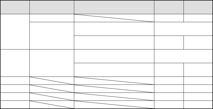
Table 4.12.3.1 Conditions for returning/discarding a component
Packaging
style
Condition 1 Condition 2 When
returning
When
discarding
32-mm feeder ○
Components whose shorter side is 1
mm or less
Inquiry *1
Tape
Tape feeders other
than the above
Components whose shorter side is 1
mm or more
○
Components whose shorter side is 1
mm or less
Inquiry *1 Bulk
Components whose shorter side is 1
mm or more
○
Holder ○
MTC ○
MTS ○
Stick ○
*1 The system displays the dialog box that asks you whether to return a
component or discard it. In Continuous Measurement mode, the system
displays this dialog box before starting measurement.
③ Selecting a feeder used to pick up a component
If two or more feeders are assigned to the same type of components in Pick data,
the system, by default, starts picking up components from one whose data was
entered first of all.
However, you can change a feeder to another one intentionally.
④ Changing the coordinates of a pick-up position
If a component is not picked up properly, manually enter the coordinates of the
component pick-up position or use the HOD device to teach these coordinates to
change them.
⑤ Manual pick-up
If there is no Pick data created, you can manually attach a component to a nozzle.
However, in this case, you cannot enter coordinates of the component pick-up
position. You cannot operate a feeder either.
4 – 212
4.12.3.4 Check operation with vision recognition
4.12.3.4.1 Operation transition during checking a component with vision recognition
The displayed screen and the system state are changed during checking a
component with the vision recognition function as shown below.
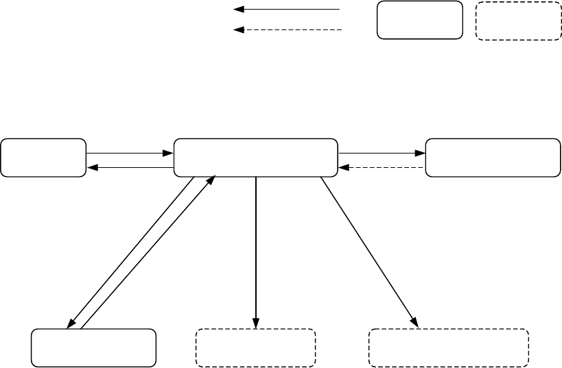
Figure 4.12.3.4.1 State transition while the system is checking a component with
vision recognition
User operation
Process
Dialog box
Process
onl
y
Check of a
component with
vision reco
g
nition
Selection
“Vision inspection” dialog
b
Return.
Check
“Executing inspection”
dialog box box
Correct/Error
Teaching
HOD device key
Feeder
ENTER/
CANCEL
PREV/NEXT
Feeder knock
Change of a component
p
ick-u
p
p
osition
4 – 213
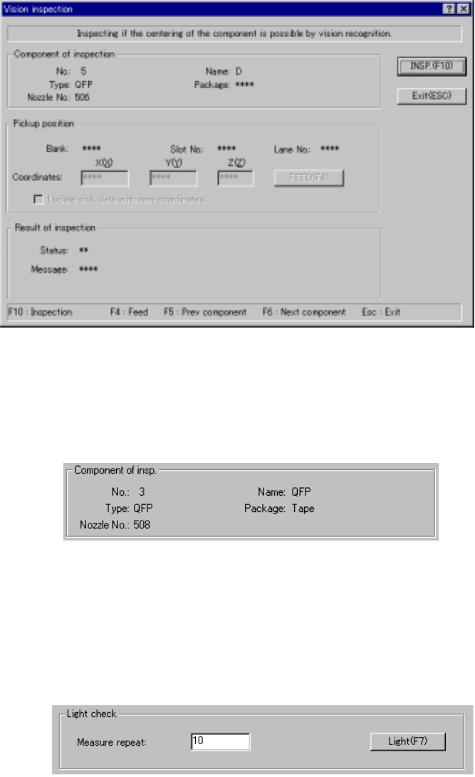
4.12.3.4.2 Vision recognition inspection operation
(1) Vision recognition operation
When you select the [Vision recognition] command, the following dialog box
appears on the screen.
Figure 4.12.3.4.2 “Vision inspection” dialog box
1) Component of insp. (inspection)
Component data required to perform the vision recognition inspection
appears on the dialog box.
Figure 4.12.3.4.3 “Component of insp.” Section
2) Light check
This button allows you to obtain the optimal brightness of the light to
improve the component recognition rate.
The system will recognize a component at least three times of the number
you set in the “Measure repeat” field.
Figure 4.12.3.4.4 <Light> button
(Note) When the system is set to measure the light according to the light
pattern (specified with the Light type Light style of the vision control
data) other than the default pattern, it may not measure the light.