KE2040Instruction Manual Ver2.01,REV04.2003.6.25.pdf - 第324页
4 – 214 3) Pickup position Data on the component pick-up posit ion appears on the dialog box. You can change the com ponent pick- up position to the pr evious or next alternate com ponent position also. If ther e is no P…
4 – 213
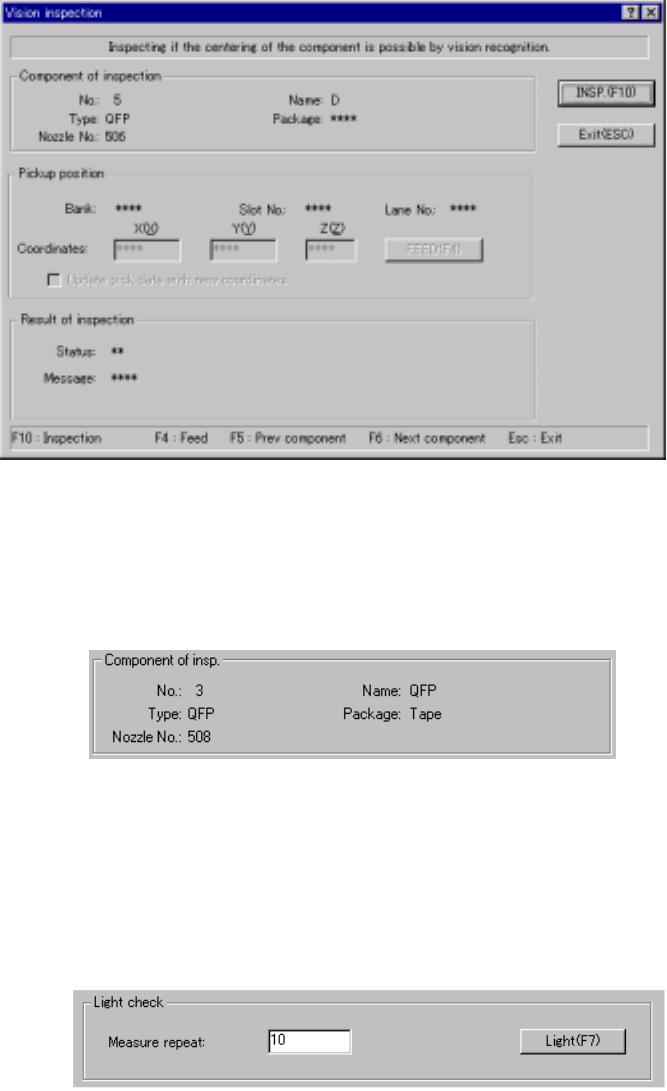
4.12.3.4.2 Vision recognition inspection operation
(1) Vision recognition operation
When you select the [Vision recognition] command, the following dialog box
appears on the screen.
Figure 4.12.3.4.2 “Vision inspection” dialog box
1) Component of insp. (inspection)
Component data required to perform the vision recognition inspection
appears on the dialog box.
Figure 4.12.3.4.3 “Component of insp.” Section
2) Light check
This button allows you to obtain the optimal brightness of the light to
improve the component recognition rate.
The system will recognize a component at least three times of the number
you set in the “Measure repeat” field.
Figure 4.12.3.4.4 <Light> button
(Note) When the system is set to measure the light according to the light
pattern (specified with the Light type Light style of the vision control
data) other than the default pattern, it may not measure the light.
4 – 214
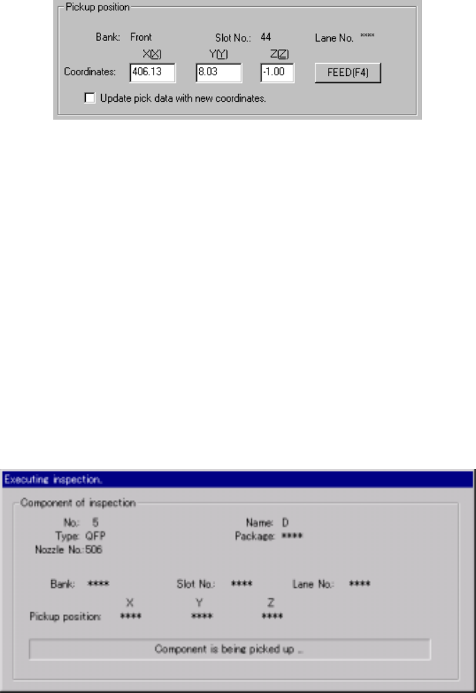
3) Pickup position
Data on the component pick-up position appears on the dialog box. You
can change the component pick-up position to the previous or next
alternate component position also. If there is no Pick data created, or if
“MTC” is specified as a feeder, each item on this section is not displayed,
so you cannot change the component pick-up position, perform the
feeder-knock operation or teaching operation.
Figure 4.12.3.4.5 Pick-up position of a component to be checked
① <FEED> button
This button knocks a feeder once to feed a component (except a
32-mm paper tape).
② “Update pick data with new coordinates”
Check this check box to use the HOD device and store the taught
result in Pick data.
If you do not check this box, the taught coordinates are applied to the
current pick-up operation only.
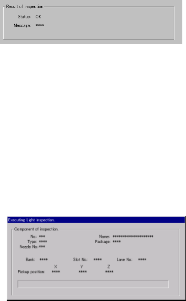
4) “Executing inspection” screen
While the system is checking a component with the vision recognition
function, the following dialog box appears on the screen. On this dialog
box, data on a component being inspected and its pick-up position are
displayed. The process being performed is also displayed.
Figure 4.12.3.4.6 “Executing inspection” screen
4 – 215
① Result of inspection
After checking a component, the system displays the result in the
“Result of inspection” section of the screen. “OK” appears if a
component can be centered based on its vision, while “NG” and the
reason of an error appear in the “Message” space if not.
Figure 4.12.3.4.7 “Result of inspection” section
② <INSP.> button
This button checks a component with the vision recognition function.
③ <Exit (ESC)> button
This button finishes checking a component with the vision recognition
function and returns to the previous screen.
5) <Light> button
When you click this button, the system measures the light.
① “Executing Light inspection” dialog box
While the system is measuring the light, the following dialog box
appears on the screen. On this dialog box, the data on a component
being measured and the component pick-up position are displayed.
Figure 4.12.3.4.8 “Executing Light inspection” dialog box