KE2040Instruction Manual Ver2.01,REV04.2003.6.25.pdf - 第355页
4 – 245 4.12.5.8 “Parameters are under acquisi tion…” dial og box W hen you click the <Acquir e> button on t he “Coplanarity inspection” dialog box, the system obtains the coplanarit y parameters, and displays the …
4 – 244
4.12.5.6 Overview of obtaining the coplanarity parameters
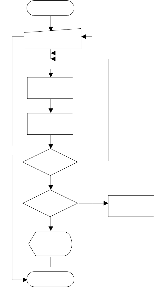
The operation flow for obtaining the coplanarity parameters is shown below.
Figure 4.12.5.4 Operation flow for obtaining the coplanarity parameters
4.12.5.7 Methods for obtaining the coplanarity parameters
If the system cannot perform a coplanarity check stably, change the threshold value
of the electrode brightness and the scanning position offset value (applicable for a
lead component only) to obtain the parameters that stabilizes measurement
operation. How any times the system measures a component becomes a multiple
of a value you entered in the “Number of times” field, and may become up to 20
times of the value you entered.
Execution of check
(on the dialog box)
Check
Check with vision
reco
g
nition
Display of the
result (on the
dialo
g
box
)
Start of obtaining
the parameters
Coplanarity check
End of obtaining
the parameters
End
Performed the
check the number
of times you set?
Judge
Change of the
parameter
4 – 245
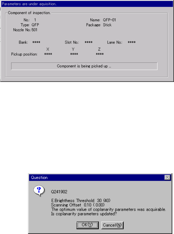
4.12.5.8 “Parameters are under acquisition…” dialog box
When you click the <Acquire> button on the “Coplanarity inspection” dialog box, the
system obtains the coplanarity parameters, and displays the following dialog box
while the system is obtaining the parameters.
Figure 4.12.5.5 “Parameters are under acquisition…” dialog box
4.12.5.9 Dialog box for showing the parameters obtained
When the system obtains the optimal coplanarity parameter, the system displays the
obtained electrode brightness threshold and scanning position offset on the screen.
The parameters set before the system obtains new ones are displayed in
parentheses. When you click the <OK> button, the system updates these
parameters to the obtained ones. When you click the <Cancel> button, the system
maintains the parameters set before obtaining new ones.
Figure 4.12.5.6 Obtained parameters dialog box
4 – 246
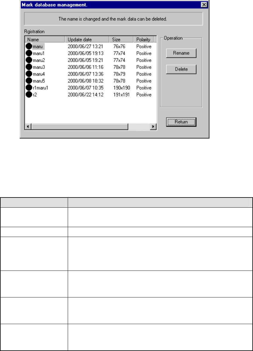
4.12.6 Mark database
This command manages the mark database which was registered during teaching of
mark data described in Chapter 5 "TEACHING".
Figure 4.12.6.1 "Mark database management" dialog box
(1) Registration
This list displays the mark data registered in the database. The meaning of
each item is described in Table below.
Item Meaning
Name Name of a mark
(The mark shape is displayed before the name itself.)
Update date Date when a mark was registered in the database.
Size Number of horizontal and vertical pixels consisting of a mark
aaa x bbb
aaa = number of horizontal pixels
bbb = number of vertical pixels
Polarity Negative/positive shot of a mark
Positive: white mark on black background
Negative: black mark on white background
Scale Image data scale of a mark
Grayscale: mark data is read as a multi-scale image.
Binaryscale: mark data is read as a binary-scale image.
Station (available to a
KE-2030 only)
Station which obtained a mark
Left = A mark was read with the OCC located on the left station.
Right = A mark was read with the OCC located on the right station.