KE2040Instruction Manual Ver2.01,REV04.2003.6.25.pdf - 第363页
4 – 253 4.14 Help This comm and invokes the online manual. 4.14.1 Version information This comm and displays the infor mation on t his prog ram (Pr ogram Editing utility). The messag e shows a corresponding version numbe…
4 – 252
4.13.3 Re-search
The "Re-search" function searches component data, pick data or vision data from the
database or the permanently supplied information again, and updates program data
with it.
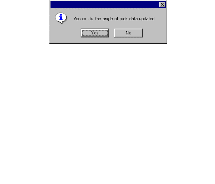
When you click the “Re-search” command, the following dialog box appears on the
screen.
◇ When you click the <Yes> button, all pick-up angles are updated.
◇ When you click the <No> button, any pick-up angle set in Pick data is not
updated.
•
When this command is executed, component data, pick data, and vision
data are updated (by overwriting). Once executed while data (component
form) is edited, this command cannot be cancelled.
•
The conditions of calling this command from the permanently supplied
information or database can be changed by the MSL set up program.
•
If a comment on the component data you called is longer than 30
characters, HLC handles the first 30 characters as a valid comment, and
copies them. If a line feed code is include in a comment on the
component data you called, HLC handles characters located after the line
feed code as invalid data, and copies characters located before the line
feed code only.
L
4 – 253
4.14 Help
This command invokes the online manual.
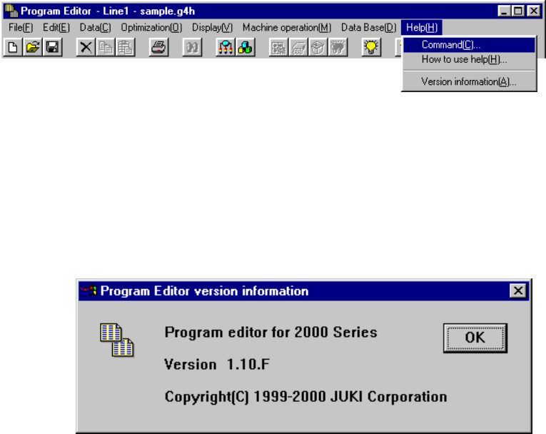
4.14.1 Version information
This command displays the information on this program (Program Editing utility).
The message shows a corresponding version number.
Example.
5 − 1
CHAPTER 5 VISION RECOGNITION
5.1 Outline
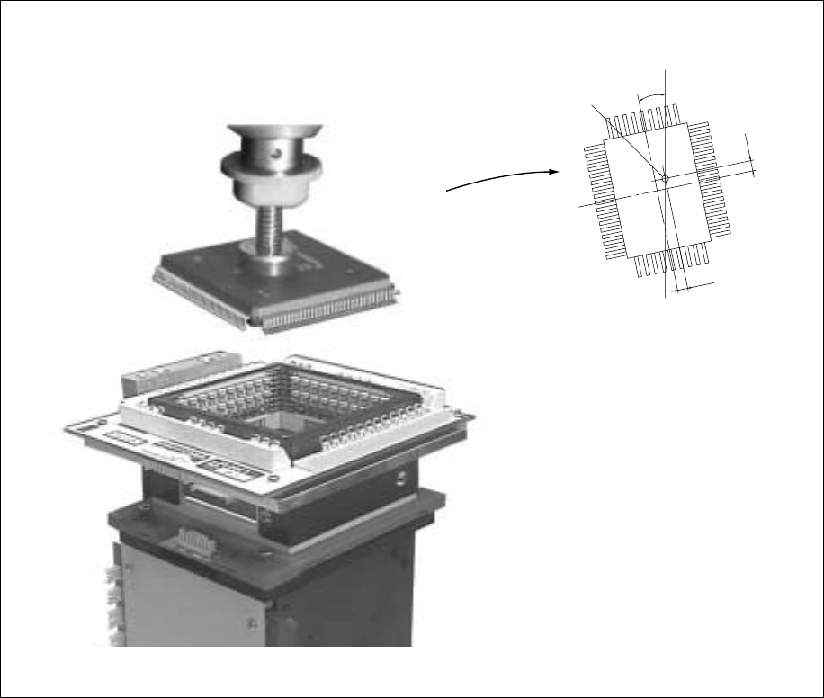
5.1.1 Position of components for vision recognition
Using the VCS camera, view the position of the component picked up with the vision
correction head to obtain the balance and angle offset of the component. At this
time, component’s bent leads are also checked as faulty. After moving to the PWB
placement point, the obtained balance and angle offsets are corrected for placement
at right balance and angle.
Figure 5.1.1.2
Center of the nozzle
θ
∆Y
∆X