KE2040Instruction Manual Ver2.01,REV04.2003.6.25.pdf - 第365页
5 − 2 5.2 Vision Data I nput V ision data is used to recog nize the component using vision recognit ion funct ion. The vision data can be entered only for the component t ypes shown below and which have been selected for…
5 − 1
CHAPTER 5 VISION RECOGNITION
5.1 Outline
5.1.1 Position of components for vision recognition
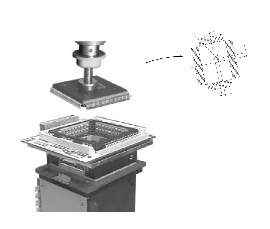
Using the VCS camera, view the position of the component picked up with the vision
correction head to obtain the balance and angle offset of the component. At this
time, component’s bent leads are also checked as faulty. After moving to the PWB
placement point, the obtained balance and angle offsets are corrected for placement
at right balance and angle.
Figure 5.1.1.2
Center of the nozzle
θ
∆Y
∆X
5 − 2
5.2 Vision Data Input
Vision data is used to recognize the component using vision recognition function.
The vision data can be entered only for the component types shown below and which
have been selected for vision centering of the component data.
QFP, SOP, TSOP, TSOP2, PLCC (QFJ), BAG, SOJ, PQFP (BQFP) one-way lead
connector, J lead socket, gull wing socket, socket with bumper, aluminum electrolytic
capacitor, and GaAsFET, two-way lead connector, SOP (with a heat sink), FBGA, Z
style lead connector
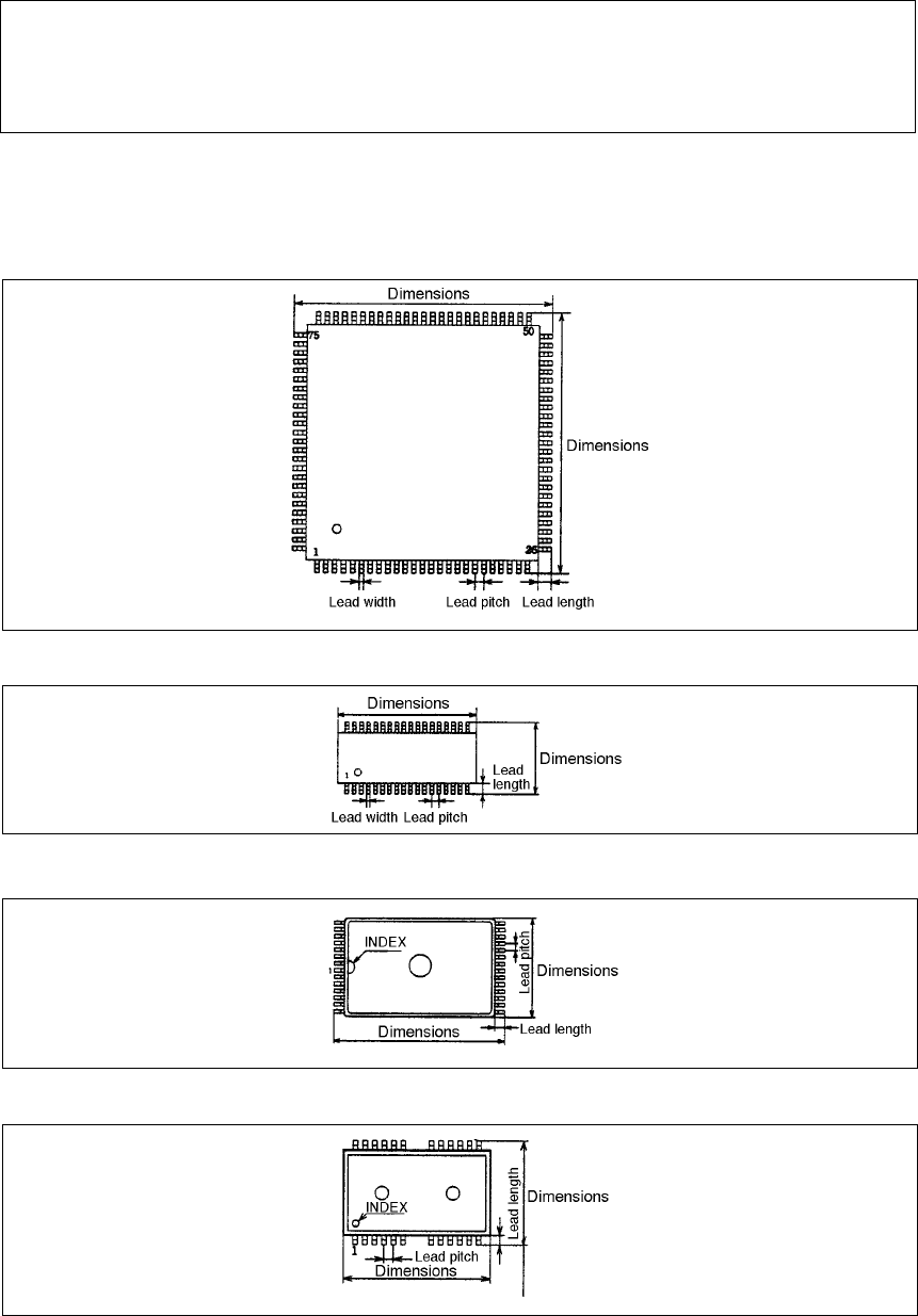
• The following shows the component types. For data setting, it is defined to 0° of
the components when the components are oriented as shown below.
① QFP (Top view)
② SOP (Top view)
③ TSOP (Top view)
④ TSOP2 (Top view)
5 − 3
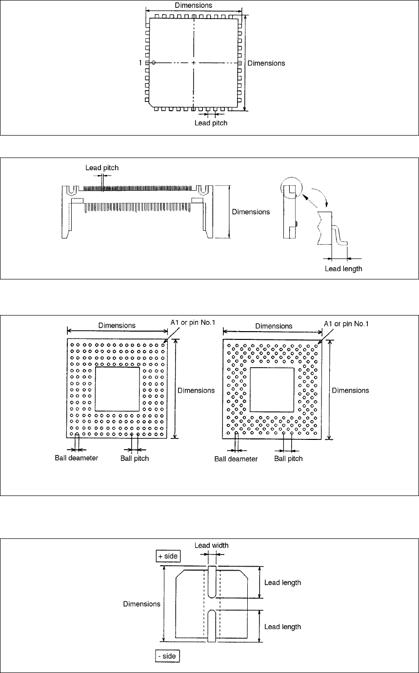
⑤ QFJ (PLCC) (Top view)
⑥ One-way lead connector (Top view)
⑦ BGA, FBGA (Bottom view)
Normal assignment Stagger assignment
Note: The ball diameter shall be entered as lead width, and ball pitch as lead pitch.
⑧ Aluminum electrolytic capacitor (Bottom view)