KE2040Instruction Manual Ver2.01,REV04.2003.6.25.pdf - 第370页
5 − 7 (1) Setti ng Items Setting item Descripti on 1 Pitch (lead pit ch) Set the lead (ball ) pitch (di stance between two consec utive leads or balls). 2 Len (lead length) Set the l ead length. 3 Wd (lead width) Set the…
5 − 6
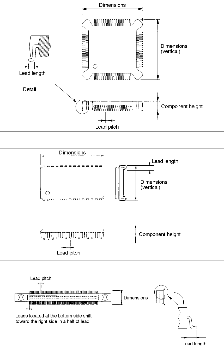
⑮ BQFP (PGFP) (Top view)
⑯ SOJ (Top view)
⑰ Z lead connector (Top view)

5 − 7
(1) Setting Items
Setting item Description
1 Pitch (lead pitch) Set the lead (ball) pitch (distance between two consecutive leads or balls).
2 Len (lead length) Set the lead length.
3 Wd (lead width) Set the lead width.
4 Bot., L, Top and R
(Number of leads/side:
bottom, left, top and right
sides)
Enter the number of leads located on each side.
5 Bend/Level
(Bent lead detection level)
Set the level for checking a bent lead with the ratio of a bent lead to the
lead pitch.
6 Missing Start/No
(Missing lead start position and
number of missing leads)
Set the first missing lead position and the number of missing leads.
7 Contrast Set the recognition pattern.
8 Base Style Set the BGA base style.
9 Ball Pattern Set the BGA recognition pattern.
10 NumLn (number of lines) Set the number of lines on which balls are located with being viewed from
the outside of a peripheral pattern.
11 Diameter/Level
(Diameter check level)
Set the level for checking the diameter of a ball.
12 Variant/Level
(Ball deformation check level)
Set the level for checking deformation of a ball.
13 View (Recognition field of view) Set the field of view range for recognizing divided images of a component.
(This item is provided for compatibility with KE-740/760 data. You cannot
set this item with any KE-2000 series of products. Set the field of view for
recognizing divided images with the setting item “Ctrl”.
14 View Field (leads to be
recognized and not recognize)
Set the range of leads to be recognized and not recognized when the
machine recognizes divided images of a component.
15 Corr. (Brightness correction) Set the threshold for recognizing an outline-recognized component.
16 Exp (Expansion) Set a general-purpose lead connector.
17 elem. (Element) Set a general-purpose vision component.
18 Ctrl (Control) Set the recognition control items.
19 Light Set the light control items.

5 − 8
5.2.1 Setting range
5.2.1.1 Lead components
(1) QFP, PQFP, PLCC (QFJ) and IC socket
Components having fine-pitch lead on four sides
Allowable setting range/Description
Setting items
Minimum Maximum
Default
value
QFP, PQFP 0.30 mm (Note 1) 1.27 mm
QFJ (PLCC) 1.27 mm 1.27 mm
1 Pitch (lead pitch)
IC socket 1.00 mm 1.27 mm
None
2
Len (lead length) 0.30 mm 3.00 mm None
3
Bot., R, Top, L (number of leads on each side) 7 (Notes 3 and 4) 128 None
4
Bend (Bent lead detecting level) 15% 20% 25% 30% None (No check) 20%
5
Missing Start/No (First missing lead/Number of
missing leads)
Up to three blocks of missing leads
can be set.
0
(2) SOP and TSOP
Components having fine-pitch leads on two sides (three sides also)
Allowable setting range/Description
Setting items
Minimum Maximum
Default
value
1
Pitch (lead pitch)
0.30 mm (Notes
1 and 3)
1.27 mm None
2
Len (lead length) 0.30 mm 3.00 mm None
3
Bot., R, Top, L (number of leads on each side) 7 (Note 3) 128 None
4
Bend (Bent lead detecting level) 15% 20% 25% 30% None (No check) 20%
5
Missing Start/No (First missing lead/Number of
missing leads)
Up to three blocks of missing leads
can be set.
0
(3) Unidirectional lead connector/Bidirectional lead connector/Z lead connector
Allowable setting range/Description
Setting items
Minimum Maximum
Default
value
1
Pitch (lead pitch) 0.30 mm (Note 1) 2.54 mm None
2
Len (lead length) 0.30 mm 3.00 mm None
3
Bot., R, Top, L (number of leads on each side) 2 (Notes 2, 3 and 5) 128 None
4
Bend (Bent lead detecting level) 15% 20% 25% 30% None (No check) 20%
5
Missing Start/No
(First missing lead/Number of missing leads)
Up to three blocks of missing leads
can be set.
0
6 View Field (Range of leads to be recognized)
Select one of the settings: “All”,
“Only the both ends lead”, and “Both
ends lead exclusion”.
All
7
L Top, R Top, L Bot., and R Bot.
(Upper left, upper right, lower left and lower right)
When you select “Only the both ends
lead” or “Both ends lead exclusion” at
the “View Fi eld” setting item, set the
number of leads here.
None
As shown in Section 5.6,
⑰
“Z lead connector” on the previous page, leads
located on the bottom side of a Z lead connector are supposed to be shifted
toward the right side by half pitch (when viewed from the top). If leads on the
top side are shifted toward the right side, specify one missing lead on the top
left side and bottom right side respectively.