KE2040Instruction Manual Ver2.01,REV04.2003.6.25.pdf - 第374页
5 − 11 Note 1: For a staggered type of BGA (see ⑦ of Section 5.2), the maximum value is 25. Note 2: The checking precision cannot be guaranteed when you select “ Ceramic” . Note 3: When you select “PW B” or “Ceram ic”, t…
5 − 10
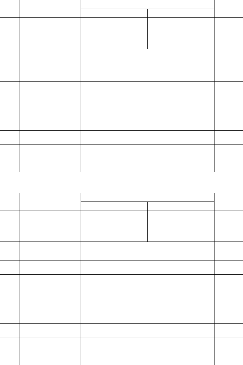
5.2.1.2 Ball components
(1) BGA
Allowable setting range/Description
Setting items
Minimum Maximum
Default
value
1
Pitch (lead pitch) 1.00 mm 3.00 mm None
2
Wd (lead width) 0.40 mm 1.00 mm None
3
Bot., R, Top, L (number of
leads on each side)
4 51 (Note 1) None
4
Missing Start/No (First
missing lead/Number of
missing leads)
Up to three blocks of missing leads can be set. 0
5
Contrast
Select one of the settings: “PWB”, “Ceramic”, “All balls” and
“All land”. (Notes 2 and 3)
All balls
6
Base Style
Select one of the settings: “Standard”, “Index mark 4
corner”, “Index mark 3 corner”, “Index mark 2 corner”, “Index
mark 1 corner”, “Outer belt type mark” and “Mark overspill
type”.
Standard
7
Ball Pattern
Select one of the settings: “Browse”, “Edit”, “Standard
BGA”, “Peripheral BGA”, “Staggered std. BGA (More out)”,
“Staggered per. BGA (More out)”, “Staggered std. BGA
(Fewer out)” and “Staggered per. BGA (Fewer out)” (*).
None
8
NumLn
For a peripheral ball pattern, set the number of lines on which
balls are located with being viewed from the outside.
None
9
Diameter/Level
Select “Yes” or “No” to check the diameter of a ball and set
the level for checking the diameter (1 to 100 %)
No (50%)
10
Variant/Level
Select “Yes” or “No” to check deformation of a ball and set
the level for checking deformation (1 to 100 %).
No (50%)
(2) FBGA
Allowable setting range/Description
Setting items
Minimum Maximum
Default
value
1
Pitch (lead pitch) 0.35 mm (Note 4) 2.00 mm None
2
Wd (lead width) 0.14 mm (Note 5) 0.63 mm None
3
Bot., R, Top, L (number of
leads on each side)
4 51 (Note 1) None
4
Missing Start/No (First
missing lead/Number of
missing leads)
Up to three blocks of missing leads can be set. 0
5
Contrast
Select one of the settings: “All balls” and “All land”. (Notes 2
and 3)
All balls
6
Base Style
Select one of the settings: “Standard”, “Index mark 4
corner”, “Index mark 3 corner”, “Index mark 2 corner”, “Index
mark 1 corner”, “Outer belt type mark” and “Mark overspill
type”.
Standard
7
Ball Pattern
Select one of the settings: “Browse”, “Edit”, “Standard
BGA”, “Peripheral BGA”, “Staggered std. BGA (More out)”,
“Staggered per. BGA (More out)”, “Staggered std. BGA
(Fewer out)” and “Staggered per. BGA (Fewer out)” (*).
None
8
NumLn
For a peripheral ball pattern, set the number of lines on which
balls are located with being viewed from the outside.
None
9
Diameter/Level
Select “Yes” or “No” to check the diameter of a ball and set
the level for checking the diameter (1 to 100 %)
No (50%)
10
Variant/Level
Select “Yes” or “No” to check deformation of a ball and set
the level for checking deformation (1 to 100 %).
No (50%)
Note: For a BGA, meaning of some setting items is changed: from “lead pitch” to “ball pitch”,
“lead width” to “ball width”, and “number of leads” to “number of balls on the outer frame”.

5 − 11
Note 1: For a staggered type of BGA (see
⑦
of Section 5.2), the maximum value is 25.
Note 2: The checking precision cannot be guaranteed when you select “ Ceramic”.
Note 3: When you select “PWB” or “Ceramic”, the machine cannot divide and recognize image of a
component. For an FBGA, “PWB” and “Ceramic” do not appear on the pop-up menu.
Note 4: The minimum ball pitch is 0.7 mm for an optional 37-mm VCS, 0.5 mm for an optional
27-mm VCS, and 0.35 mm for an optional 18-mm VCS.
Note 5: The minimum ball diameter is 0.28 mm for an optional 37-mm VCS, 0.2 mm for an optional
27-mm VCS, and 0.14 mm for an optional 18-mm VCS.
Notes:
The machine cannot recognize a component if:
①
the machine does not detect any clear contrast between a solder ball and a
board on which a solder ball is mounted,
②
the machine does not recognize a ball alone because a pattern whose
diameter is the same as that of a solder ball is connected to a solder ball, or
③
there is a through-hole whose diameter is the same as that of a solder ball on
a board on which a solder ball is mounted.
5 − 12
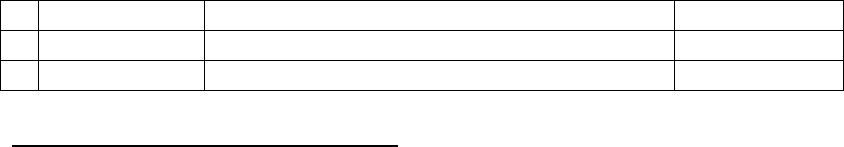
5.2.1.3 Outline-recognized components
(1) Outline recognition
Setting item Allowable setting range/Description Default value
1
Contrast Select one of the settings: “4sides”, “4corners” and “Center”. 4sides
2
Corr. -127 to 127 0
Note: Outline-recognized components
1) Component size (with a reflective light)
- Maximum component size: 50 mm x 50 mm
- Maximum component size recognized with optional VCSs
Optional 37-mm VCS: 34 mm x 34 mm
Optional 27-mm VCS: 24 mm x 24 mm
Optional 18-mm VCS: 15.5 mm x 15.5 mm
- Minimum component size: 3 mm x 3 mm
2) Component size (with a penetrative light)
- Maximum component size: 35 mm x 35 mm
- Minimum component size: 9 mm x 9 mm
Note that only the standard VCS can divide and recognize image of an
outline-recognized component.