KE2040Instruction Manual Ver2.01,REV04.2003.6.25.pdf - 第375页
5 − 12 5.2.1.3 O utline- recognized components (1) Outli ne recognition Setting item A l lowabl e setting range/Descripti on Default value 1 Contrast S elect one of the set tings : “4s ides”, “4c orners” and “Center”. 4s…

5 − 11
Note 1: For a staggered type of BGA (see
⑦
of Section 5.2), the maximum value is 25.
Note 2: The checking precision cannot be guaranteed when you select “ Ceramic”.
Note 3: When you select “PWB” or “Ceramic”, the machine cannot divide and recognize image of a
component. For an FBGA, “PWB” and “Ceramic” do not appear on the pop-up menu.
Note 4: The minimum ball pitch is 0.7 mm for an optional 37-mm VCS, 0.5 mm for an optional
27-mm VCS, and 0.35 mm for an optional 18-mm VCS.
Note 5: The minimum ball diameter is 0.28 mm for an optional 37-mm VCS, 0.2 mm for an optional
27-mm VCS, and 0.14 mm for an optional 18-mm VCS.
Notes:
The machine cannot recognize a component if:
①
the machine does not detect any clear contrast between a solder ball and a
board on which a solder ball is mounted,
②
the machine does not recognize a ball alone because a pattern whose
diameter is the same as that of a solder ball is connected to a solder ball, or
③
there is a through-hole whose diameter is the same as that of a solder ball on
a board on which a solder ball is mounted.
5 − 12
5.2.1.3 Outline-recognized components
(1) Outline recognition
Setting item Allowable setting range/Description Default value
1
Contrast Select one of the settings: “4sides”, “4corners” and “Center”. 4sides
2
Corr. -127 to 127 0
Note: Outline-recognized components
1) Component size (with a reflective light)
- Maximum component size: 50 mm x 50 mm
- Maximum component size recognized with optional VCSs
Optional 37-mm VCS: 34 mm x 34 mm
Optional 27-mm VCS: 24 mm x 24 mm
Optional 18-mm VCS: 15.5 mm x 15.5 mm
- Minimum component size: 3 mm x 3 mm
2) Component size (with a penetrative light)
- Maximum component size: 35 mm x 35 mm
- Minimum component size: 9 mm x 9 mm
Note that only the standard VCS can divide and recognize image of an
outline-recognized component.
5 − 13
5.2.2 Basic operation
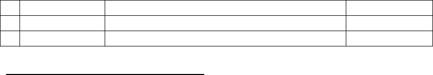
Vision data is displayed in two ways: in the list format and the form format.
Select the [Display] command form the menu bar on the Program Editor windows,
and select the [Vision Form] or [Vision List] command on the displayed menu.
− When you double-click on the Vision List displayed on the screen, the “Vision
Form” appears also.
* A check mark appears next to the menu item [Vision List] when the Vision list
screen is displayed while it appears next to the menu item [Vision Form]
when the Vision form screen is displayed.
Figure 5.2.2 Selecting Vision data screen format
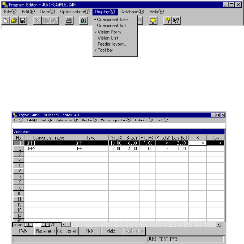
5.2.2.1 Vision list screen
Sample Vision data and its basic operation are shown below.
Figure 5.2.2.1 Vision List screen
− Description of basic operation
① Input focus
A line on which the input focus is located is reverse-displayed, while a cell in
which the input focus is located is not.
◇ An input character is echoed back onto the formula bar as you enter it.
When you validate it, it is entered in a cell.
② Cursor movement range
Column: The cursor can move to any line on which a component name is
entered. You cannot move the input field to any line on which a
component name is entered yet.
Row: The cursor can move between the rows “Type” and “Contrast”.