KE2040Instruction Manual Ver2.01,REV04.2003.6.25.pdf - 第379页
5 − 16 ④ Quitting the Vision form screen W hen you click t he <OK> butt on, the system validates data and displays the V ision list screen ag ain. W hen you click the <CANCEL> butt on, the system r estores da…
5 − 15
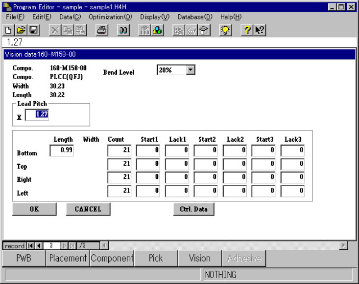
5.2.2.2 Vision Form screen
Sample Vision data and its basic operation are shown below.
Figure 5.2.2.2 Vision Form screen
−
−−
− Description of basic operation
① On the window
You can edit data whose entry field does not have an asterisk “*” mark on the
Vision list screen.
The menu items (displayed items) you can edit vary depending on the entered
component type. A blank appears in a field having a value exceeding the
input range is entered.
② Range the cursor moves
To move the input focus to the desired item, press the <TAB> key or <SHIFT>
+ <TAB> keys.
When the input focus is located in the edit box, the input range appears on the
lower left-hand corner of the screen.
③ Scroll bar
When you press the [Page Up] key, the previous vision data appears on the
screen.
When you press the [Page Down] key, the next vision data appears on the
screen.
You can change the displayed data in the same manner by operating the
record box also.
5 − 16
④ Quitting the Vision form screen
When you click the <OK> button, the system validates data and displays the
Vision list screen again.
When you click the <CANCEL> button, the system restores data to the
conditions before your editing without validating it, and opens the Vision list
screen.
When you switch the Vision form screen to another screen with a method
other than the <CANCEL> button (that is, by the menu item or button
displayed on the screen), the system validates the data by assuming that you
click the <OK> button.
⑤ Available “Edit” commands
The commands displayed on the “Edit” menu, [Jump], [Search] and [Change
Component Name] are available. You can use these commands in the same
manner as those on the Vision list screen.
⑥ Entering data
The general flow of data creation is the same as that on the Vision list screen.
See Section 5.2.3 “Detailed description of operation” for the details of how to
enter data.
⑦ Others
When you click the “Ctrl” or “elem.” field, its corresponding edit dialog box
opens on the screen. How to operate each dialog box is the same as that on
the Vision list screen.
−
−−
− Operations for each component type
The displayed menu items may vary depending on the entered component type.
This section describes the differences only.
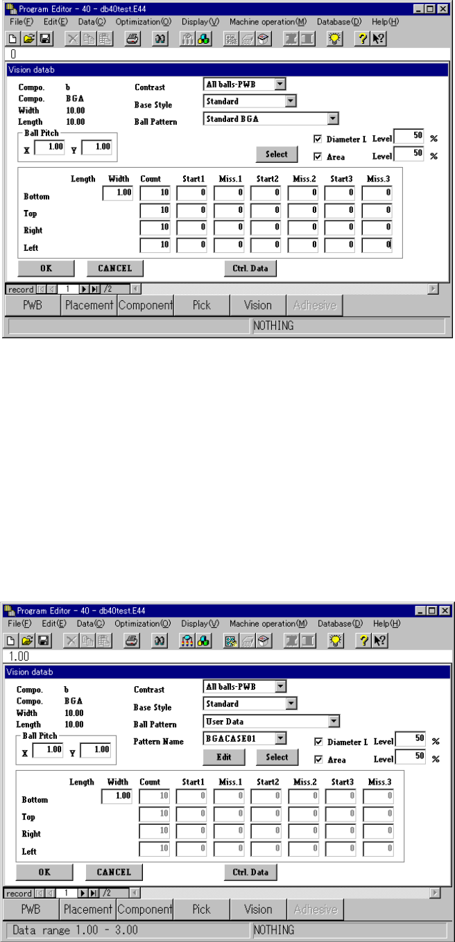
① Vision data on a BGA component
The screen shown below indicates the Vision form screen of a BGA
component.
◆ When “All land” is selected in the “Contrast” field
“Base Style” and “Ball Pattern”: the menu items “Row” and “Column” are
displayed.
(The menu items “Row” and “Column” are displayed only, and you cannot
change the displayed data.)
When you select “Peripheral BGA” in the “Ball Pattern” menu item, the menu
item [NumLn] appears on the screen.
When you select “All balls” in the “Contrast” field, the check boxes “Diameter L
Level” and “Area Level” are displayed in addition to the menu items described
above. (See Figure 5.2.2.2.2-2 “Example 1.”)
When you put a check mark in the “Diameter L Level” and/or “Area Level”
check box(es), the corresponding input level appears on the screen.
5 − 17
Figure 5.2.2.2.2-2 Example 1
−
−−
− When you select “User Data” in the “Ball Pattern” field, the ball pattern edit
function starts up if you have not set the corresponding user data yet.
Otherwise, the ball pattern name appears below the <Edit> and <Select>
buttons. (See Figure 5.2.2.2-3 “Example 2.”)
If you click the <Edit> button when another pattern is selected, the ball pattern
edit function starts up also. How to operate this function is the same as that
when you start it up on the Vision list screen.
Figure 5.2.2.2.2-3 Example 2