KE2040Instruction Manual Ver2.01,REV04.2003.6.25.pdf - 第383页
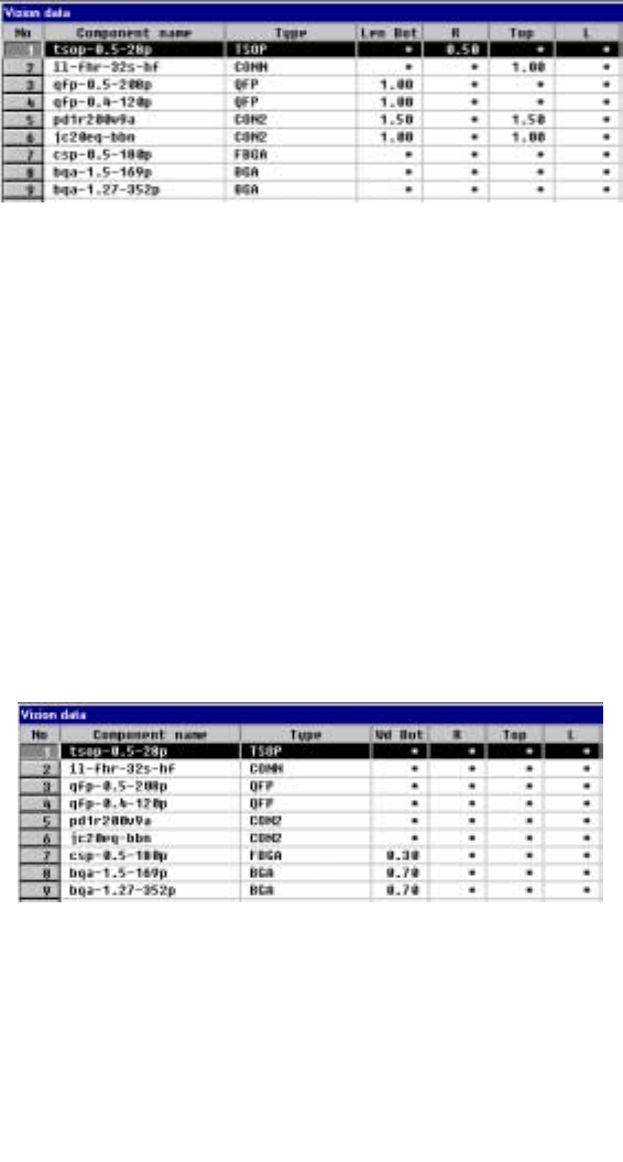
5 − 20 ⑥ Len Bot, R, T op and L Ent er the leng th of a lead section that is in contact with a board fr om the for mula bar . W hen an ast erisk m ark * is displayed in a cell, you do not have to enter any data to t his …
5 − 19
5.2.3 Detailed description of operation
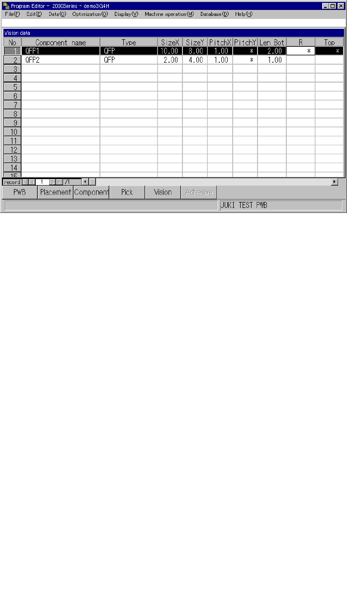
When you invoke Vision data for the first time, data appears in the “Component
name”, “Type”, “SizeX” and “SizeY” cells only.
Figure 5.2.3.1 Vision data initial screen
(1) How to set the items
① Component name
A component name entered on the Placement data screen appears in this cell.
② Type
A component type entered on the Component data screen appears in this cell.
③ Size X
The width of a component, which was entered on the Component data screen,
appears in this cell.
④ Size Y
The length of a component, which was entered on the Component data screen,
appears in this cell.
⑤ 1) PitchX
Enter the horizontal pitch between two consecutive leads (balls) from the
formula bar. The input range varies depending on the component type.
2) PitchY
Enter the vertical pitch between two consecutive leads (balls) from the
formula bar. The input range varies depending on the component type.
Figure 5.2.3.2 Pitches applied to each component type
Ball pitch
(Normal assignment)
Ball pitch
(Stagger assignment)
5 − 20
⑥ Len Bot, R, Top and L
Enter the length of a lead section that is in contact with a board from the
formula bar. When an asterisk mark * is displayed in a cell, you do not have
to enter any data to this cell.
- When a component has leads on its two or more sides, enter the length of
a lead on one side only if the length of leads on each side is the same as
each other.
- Data in the “Bot, R, Top and L” cells is based on the component feeding
angle with referring the final component feeding direction.
• The side whose lead length should be entered and the range of
the lead length vary depending on the setting of the “Type” item.
Figure 5.2.3.3 Entering the lead length from the formula bar
Figure 5.2.3.4 Range of the lead length
⑦ Wd Bot, R, Top, L (lead or ball width)
Set the width of leads on each side: bottom, right, top and left sides in this
order. The side whose lead width should be entered and the range of the
lead width vary depending on the setting of the “Type” item.
• For a ball component, enter the diameter of a ball.
Figure 5.2.3.5 Entering the lead (ball) width
Figure 5.2.3.6 Lead (ball) width
5 − 21
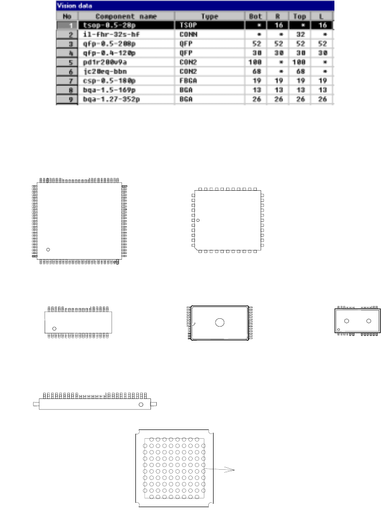
⑧ Bot, R, Top and L (bottom, right, top and left)
Enter the number of leads on each side: bottom, right, top and left sides in this
order. When an asterisk mark * appears in a cell, you do not have to enter
any data to the cell.
- The input range of the number of leads varies depending on the setting of
the “Type” setting item.
- For a ball component, enter the number of balls located on the outer frame.
If you do not set the same number of balls for all sides, the largest value is
regarded as valid.
Figure 5.2.3.7 Entering the number of leads on the top,
bottom, left and right sides.
外周のボール数
Figure 5.2.3.8 Explanation of the top, bottom, left
and right sides of each component type
上
下
左右
上
右
左
下
上
下
左右
上
下
上
Top
Right
Bottom
Left
1
Balls located on the outer frame
Top
Bottom
Top
Bottom
Right
Left
Top
Bottom
1
Top
Right
Left