KE2040Instruction Manual Ver2.01,REV04.2003.6.25.pdf - 第385页
5 − 22 ⑨ Bend W hen t he machine detects a bent lead, it discards t he component having a bent lead onto the I C discard position as operat ion for an error . Ent er the level for det ecting a bent lead here. - W hen dat…
5 − 21
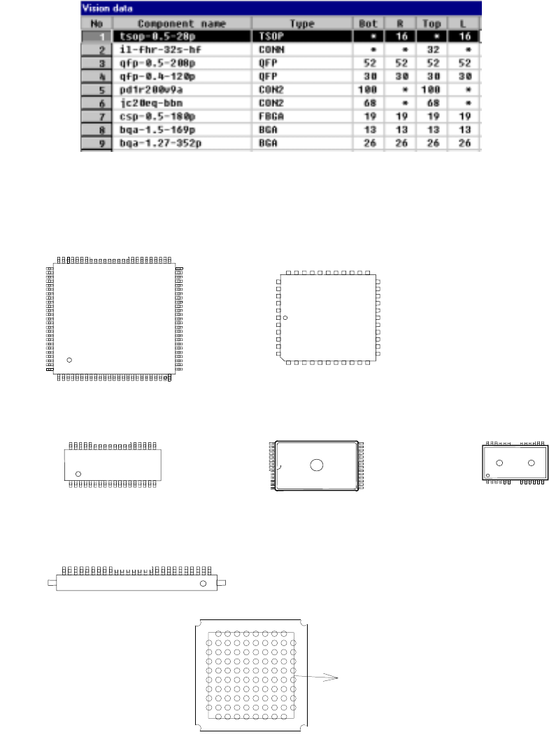
⑧ Bot, R, Top and L (bottom, right, top and left)
Enter the number of leads on each side: bottom, right, top and left sides in this
order. When an asterisk mark * appears in a cell, you do not have to enter
any data to the cell.
- The input range of the number of leads varies depending on the setting of
the “Type” setting item.
- For a ball component, enter the number of balls located on the outer frame.
If you do not set the same number of balls for all sides, the largest value is
regarded as valid.
Figure 5.2.3.7 Entering the number of leads on the top,
bottom, left and right sides.
外周のボール数
Figure 5.2.3.8 Explanation of the top, bottom, left
and right sides of each component type
上
下
左右
上
右
左
下
上
下
左右
上
下
上
Top
Right
Bottom
Left
1
Balls located on the outer frame
Top
Bottom
Top
Bottom
Right
Left
Top
Bottom
1
Top
Right
Left
5 − 22
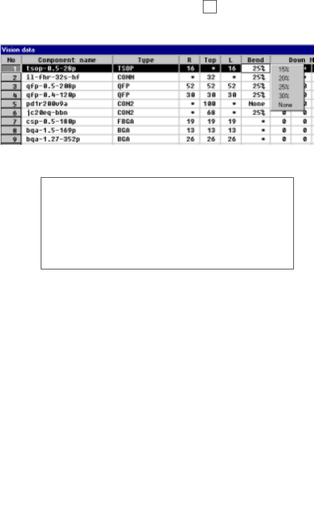
⑨ Bend
When the machine detects a bent lead, it discards the component having a
bent lead onto the IC discard position as operation for an error. Enter the
level for detecting a bent lead here.
- When data is entered to the setting item “Type”, the default value is
automatically set here.
- To change the default value, press the F2 key, then select a value from the
displayed list.
Figure 5.2.3.9 Specifying the level for detecting a bent lead
Definition of the bent lead detecting level
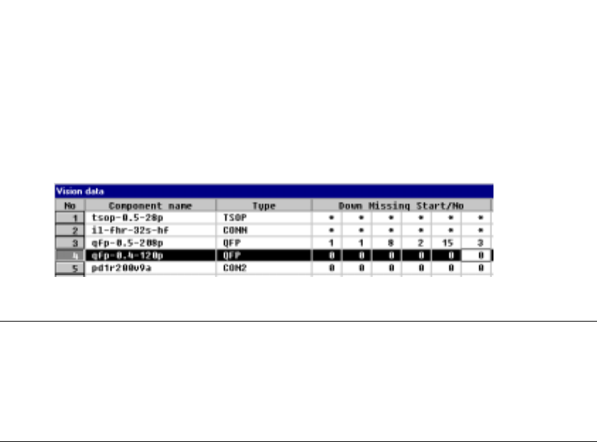
⑩ Down Missing Start/No, Right Missing Start/No,
Top Missing Start/No, Left Missing Start/No
Specify the missing leads by setting the missing lead position and the number
of missing leads. The value to be set as the setting item “number of leads”
includes the missing leads.
- Up to three blocks of missing leads can be set per side.
- When a component has no missing leads, set 0/0.
- Set the first missing lead position obtained with counting it anti-clockwise as
shown below.
Figure 5.2.3.10.1 Lead counting direction on each side
5 − 23
• The following Figure 5.2.3.10.2 shows a QFP component whose bottom side
has a missing lead(s).
<Example> Missing pins on the bottom side: Pins 1, 8, 9, 15, 16 and 17
Figure 5.2.3.10.2 Lead setting example
Notes
①
For a BGA component, specify the number of missing balls located on the
outer frame only.
②
For a BGA component, the missing balls should be viewed from the bottom
(rear), then set.