KE2040Instruction Manual Ver2.01,REV04.2003.6.25.pdf - 第386页
5 − 23 • The f ollowing Figur e 5.2.3.10. 2 shows a QFP component whose bottom side has a missing lead(s) . <Example> Missing pins on the bottom side: Pins 1, 8, 9, 15, 16 and 17 Figure 5.2.3.10. 2 Lead setting exa…
5 − 22
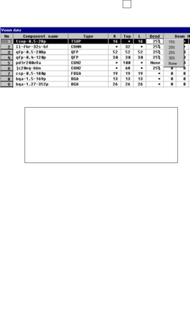
⑨ Bend
When the machine detects a bent lead, it discards the component having a
bent lead onto the IC discard position as operation for an error. Enter the
level for detecting a bent lead here.
- When data is entered to the setting item “Type”, the default value is
automatically set here.
- To change the default value, press the F2 key, then select a value from the
displayed list.
Figure 5.2.3.9 Specifying the level for detecting a bent lead
Definition of the bent lead detecting level
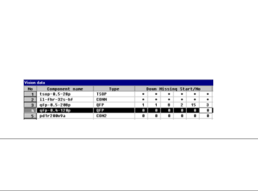
⑩ Down Missing Start/No, Right Missing Start/No,
Top Missing Start/No, Left Missing Start/No
Specify the missing leads by setting the missing lead position and the number
of missing leads. The value to be set as the setting item “number of leads”
includes the missing leads.
- Up to three blocks of missing leads can be set per side.
- When a component has no missing leads, set 0/0.
- Set the first missing lead position obtained with counting it anti-clockwise as
shown below.
Figure 5.2.3.10.1 Lead counting direction on each side
5 − 23
• The following Figure 5.2.3.10.2 shows a QFP component whose bottom side
has a missing lead(s).
<Example> Missing pins on the bottom side: Pins 1, 8, 9, 15, 16 and 17
Figure 5.2.3.10.2 Lead setting example
Notes
①
For a BGA component, specify the number of missing balls located on the
outer frame only.
②
For a BGA component, the missing balls should be viewed from the bottom
(rear), then set.
5 − 24
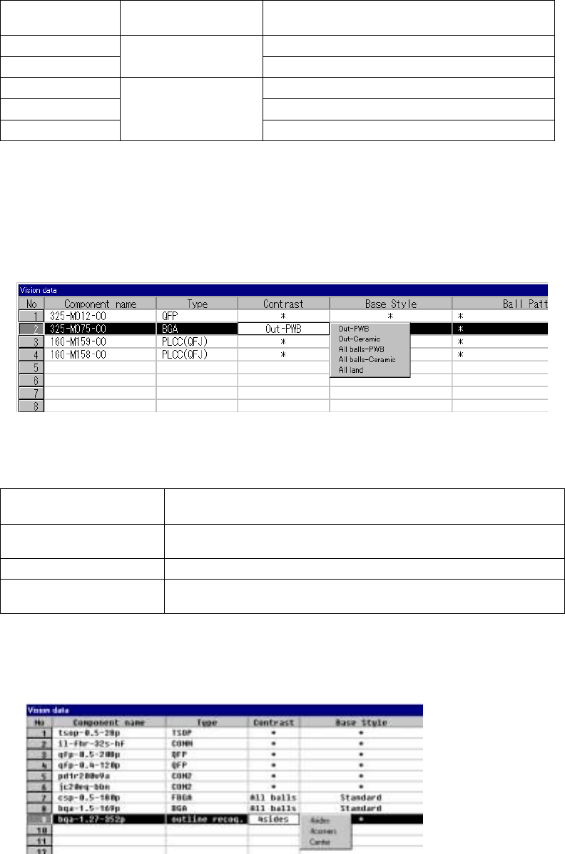
⑪ Contrast
Set the “contrast between a pin (ball) and molding section of a BGA
component”, or set the “recognition pattern for an outline-recognized
component”.
1) For a BGA
• Setting items
Table 5.5.3.1
Selection on the
pop-up menu
Recognition range Type
Out– PBW PWB type whose molding section looks black
Out– Ceramic
Recognizes balls on
the outer frame only.
Ceramic type whose molding section looks white
All balls – PWB Ball recognition by a pattern
All balls – Ceramic Ceramic type ball recognition by pattern
All land
Recognizes all balls of a
component.
All land recognition of an LGA
If you change the setting of this item to “PWB” or “Ceramic” after you
select “All balls” or “All land” and set a ball pattern, the ball pattern is
initialized.
• How to set
When you click this setting item with the right button, the selection
pop-up menu appears on the screen.
2) For an outline-recognized component
• Setting items
Table 5.2.3.2
Selection on the pop-up
menu
Recognition method
4sides
Recognizes a component with four sides of a rectangle. This setting is
effective for a rectangle component whose corner is unclear.
4corners Recognizes a component with four corners of a rectangle.
Center
Recognizes a component by calculating the center of the substance which
is currently being shot.
• How to set
When you click this setting item with the right button, the selection
pop-up menu appears on the screen.