KE2040Instruction Manual Ver2.01,REV04.2003.6.25.pdf - 第394页
5 − 31 • W hen index balls are located on the ball g rid, t he machine handles such a component as the “ S tandard” type. • W hen an index ball is outside the ball gr id, the m achine handles such a component as one of t…
5 − 30
• Setting items
Selection on the
pop-up menu
Base style
Browse Displays sample images: from “Standard” to “Mark over spill”, and allows
you to select the desired style from the displayed images.
Standard There are only balls located on the outer frame of a package.
This setting is available for a conventional BGA whose pitch is narrow and
whose balls are small. This is available also for a component whose
index balls are on the grid.
Index mark 4 corner There are only balls and index balls on the outer frame of a package, and
index balls are outside the grid.
Index balls are located at four corners outside the grid.
Index mark 3 corner There are only balls and index balls on the outer frame of a package, and
index balls are outside the grid.
Index balls are located at three corners outside the grid (when there is no
index ball at the lower left corner, it should be called 0 degrees).
Index mark 2 corner There are only balls and index balls on the outer frame of a package, and
index balls are outside the grid.
Index balls are located at two corners outside the grid (when there is no
index ball at the lower left and right corners, it should be called 0 degrees).
Index mark 1 corner There are only balls and index balls on the outer frame of a package, and
index balls are outside the grid.
Index balls are located at one corner outside the grid (when there is no
index ball at the lower right corner, it should be called 0 degrees).
Outer belt type mark There is something whose density is similar with a ball like a belt on the
outer frame of a package.
Mark over spill There is something other than a ball on the outer frame of a package.
Note: An index mark is not a ball but a mark that indicates a certain position, or
ball-shaped substance used for partial pressure.
− Default base style sample image
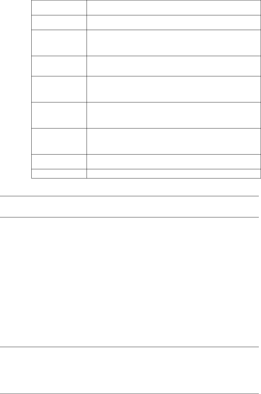
Note: The size of an index ball varies and the center of an index ball and that of a
ball are not always aligned with each another on a line. To clearly identify
each setting of “Index mark 4 corner”, “Index mark 3 corner”, “Index mark 2
corner” and “Index mark 1 corner”, we define the index ball position and its
corresponding setting as follows.
5 − 31
• When index balls are located on the ball grid, the machine handles such a
component as the “Standard” type.
• When an index ball is outside the ball grid, the machine handles such a
component as one of types: “Index mark 1 corner” to “Index mark 4 corner”
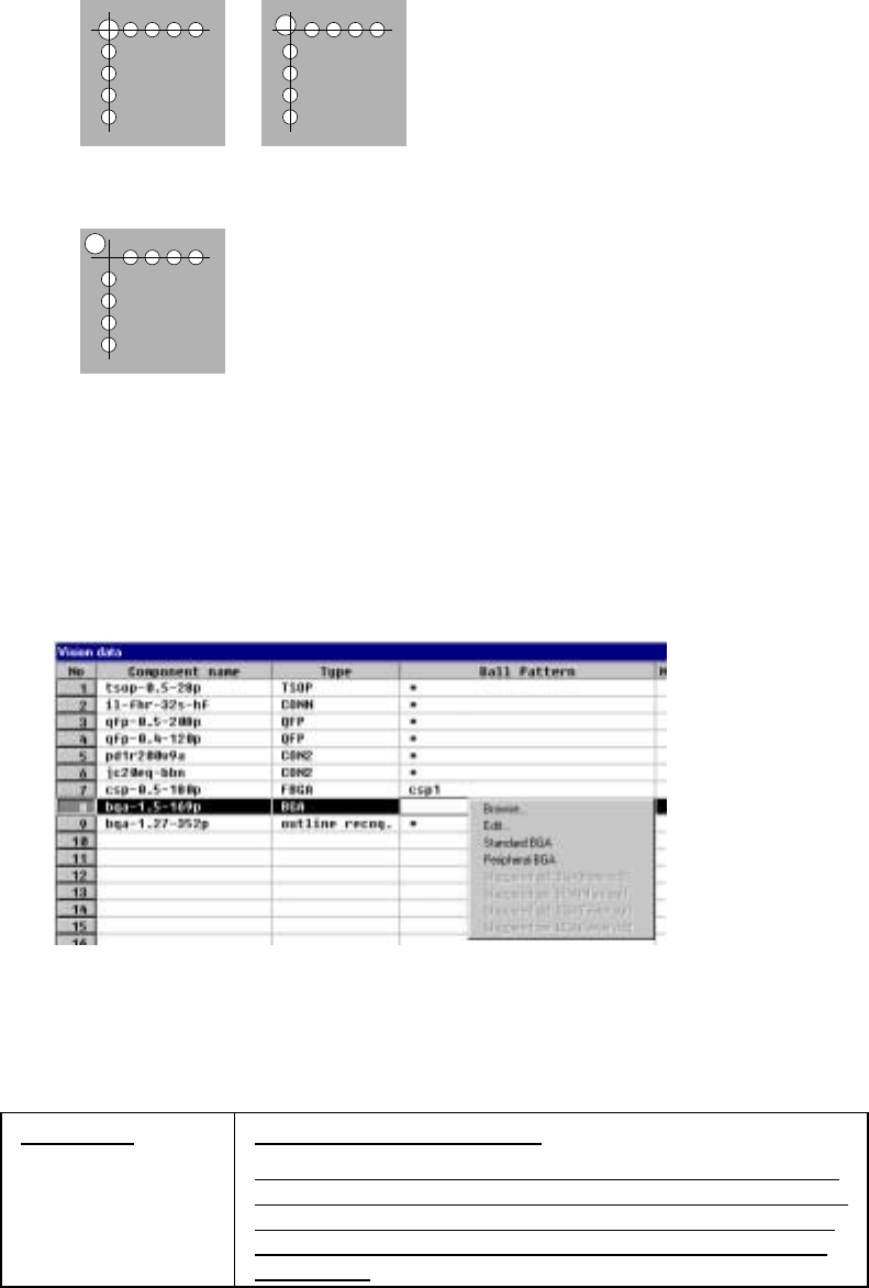
⑬ Ball pattern
Set the recognition pattern of a BGA component.
This setting item is available only when you select “All balls” or “All land” at the
“Contrast” setting item.
• When you click this item with the right button, the pop-up menu appears on
the screen as shown below.
Figure 5.2.3.22 BGA component recognition pattern setting
- When you want to use a default pattern, select one from the pop-up
menu shown above.
Ball Pattern Specify the ball pattern name.
If the number of leads (balls) is different from that of the ball
pattern you specified, HLC regards the number of balls of the
specified ball pattern as a valid value to set it to the number
of leads (balls) and the number of missing leads (balls) (all
set to zero).
5 − 32
1) Default patterns
A default pattern is a ball pattern built into the machine by default. The
following default patterns are provided. The available default patterns vary
depending on the lead (ball) pitch you entered.
Type Default pattern Selection conditions (Ball pitch range)
1 Standard BGA 1.00 mm to 1.99 mm
2 Peripheral BGA 1.00 mm to 1.99 mm
3 Staggered std. BGA (More Out)
(More balls are located on the outer frame)
2.00 mm to 3.00 mm
4 Staggered std. BGA (Fewer Out)
(Fewer balls are located on the outer
frame)
2.00 mm to 3.00 mm
5 Staggered per. BGA (More Out) 2.00 mm to 3.00 mm
6 Staggered per. BGA (Fewer Out) 2.00 mm to 3.00 mm
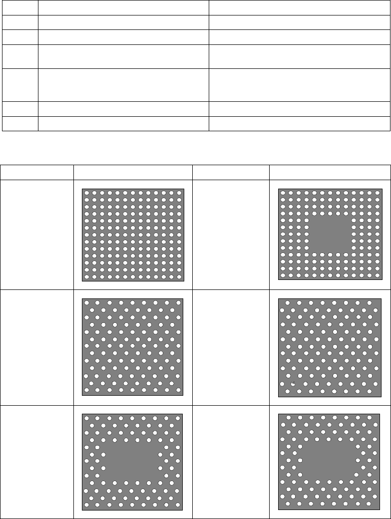
2) Default pattern sample images
Default pattern Sample image Default pattern Sample image
1. Standard
BGA
2. Peripheral
BGA
3. Stagger Std.
BGA
(More OUT)
4. Stagger Std.
BGA
(Fewer OUT)
5. Stagger Per.
BGA
(More OUT)
6. Stagger Per.
BGA
(Fewer OUT)