KE2040Instruction Manual Ver2.01,REV04.2003.6.25.pdf - 第406页
5 − 43 Recognized Recognized Recognized Recognized Recognized Recognized The leads located at the inside are not recognized. Recognized Recognized The leads located on the outside are not recognized. ⑰ V iew Fiel d, L T …
5 − 42
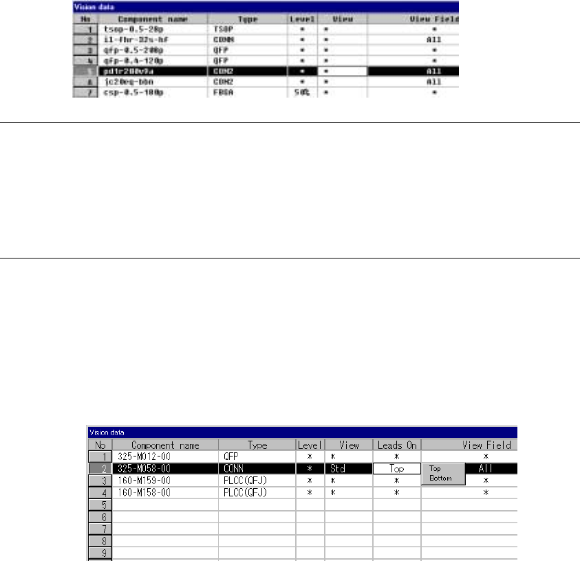
⑮ View
Set the field of view range when you want to recognize a component with
dividing its image.
- When you click this item with the right button, the selection pop-up menu
appears on the screen.
- You can select one of the settings: “Standard”, “Vertical 2”, and “Vertical
3”.
Notes:
①
This item is provided for compatibility with KE-740/760 data only. You cannot
set this item with any KE-2000 series of product.
For the field of view range, set the “Split Recognition” field of the “Vision
Control” dialog box.
②
Only the standard VCS can recognize a connector with dividing its image.
⑯ Lead direction
Set the lead direction.
Clicking the right button of the mouse displays the selection popup.
Select Up or Down as the lead direction.
5 − 43
Recognized
Recognized
Recognized
Recognized
Recognized
Recognized
The leads located at the inside are not recognized.
Recognized
Recognized
The leads located on the outside are not recognized.
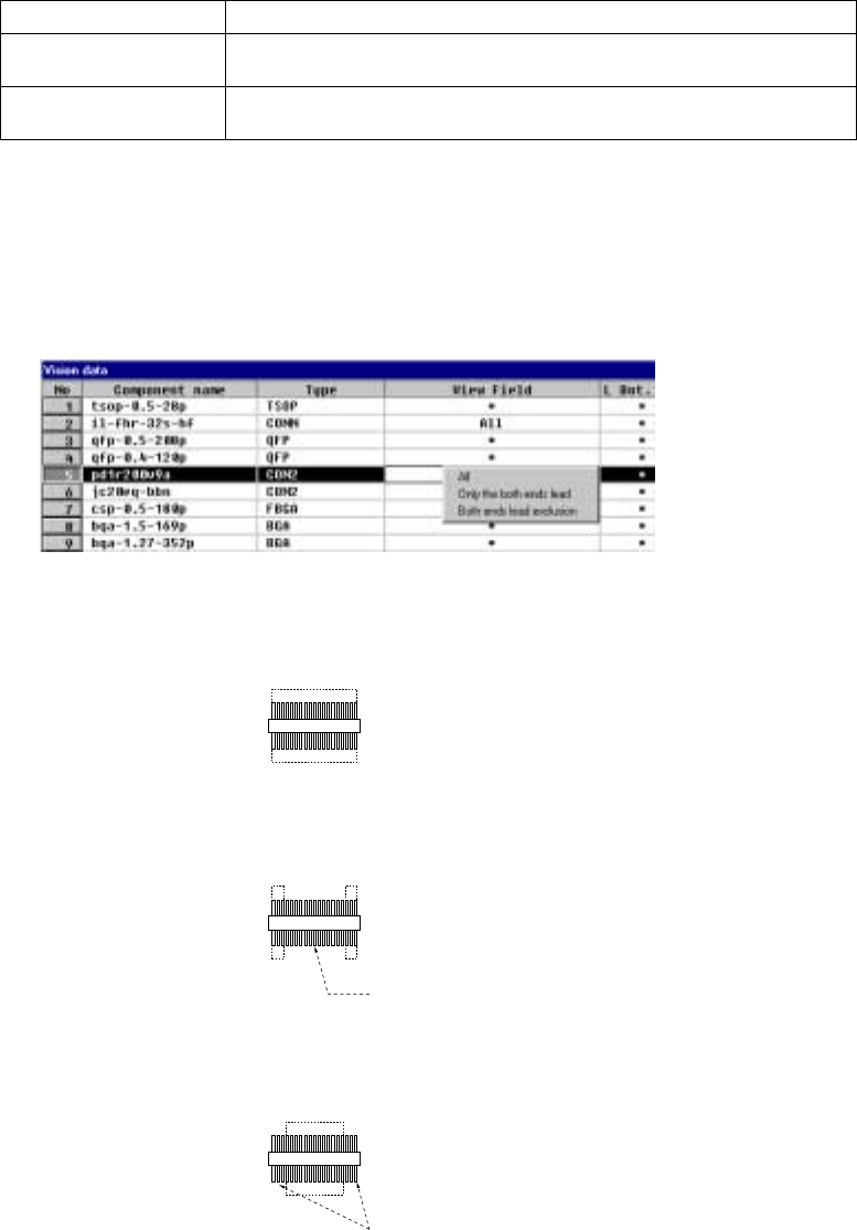
⑰ View Field, L Top, R Top, L Bot., and R Bot.
Set the range of leads to be recognized and that not recognized of a
connector.
When you click this setting item with the right button, the selection pop-up
menu appears on the screen.
All Recognizes all leads.
Only the both ends lead Specify the range of leads to be recognized with being viewed from the leads
on both ends.
Both ends lead exclusion Specify the range of leads not recognized with being viewed from the leads
on both ends.
- When you select “Only the both ends lead” or “Both ends lead exclusion”,
enter the number of leads on each side to the “L Top”, “R Top”, “L Bot.”, and
“R Bot.” fields to specify the range of leads recognized or not recognized.
- When you select “All”, you cannot specify the range of the number of leads.
1) Meaning and image of each lead recognition pattern
・ All leads: All leads are to be recognized.
・ Only the both ends lead:
Only leads located on both sides are to be recognized.
・ Both ends lead exclusion:
Leads except the specified leads located on both sides are to be
recognized.
5 − 44
2) Number of leads to be recognized
Enter the number of leads at each corner to be recognized. See the
conditions for entering the number of leads shown in Table 5.2.3.16 below.
Table 5.2.3.16.1 Range of the number of leads
Range of the number of leads
Component type Recognition pattern
Upper
left
corner
Upper
right
corner
Lower
left
corner
Lower
right
corner
Unidirectional
connector
All
Only the both ends lead
Both ends lead exclusion
****
1-3
0-3
****
1-3
0-3
****
****
****
****
****
****
Bidirectional
connector
Z-shaped lead
connector
All
Only the both ends lead
Both ends lead exclusion
****
1-3
0-3
****
1-3
0-3
****
1-3
0-3
****
1-3
0-3
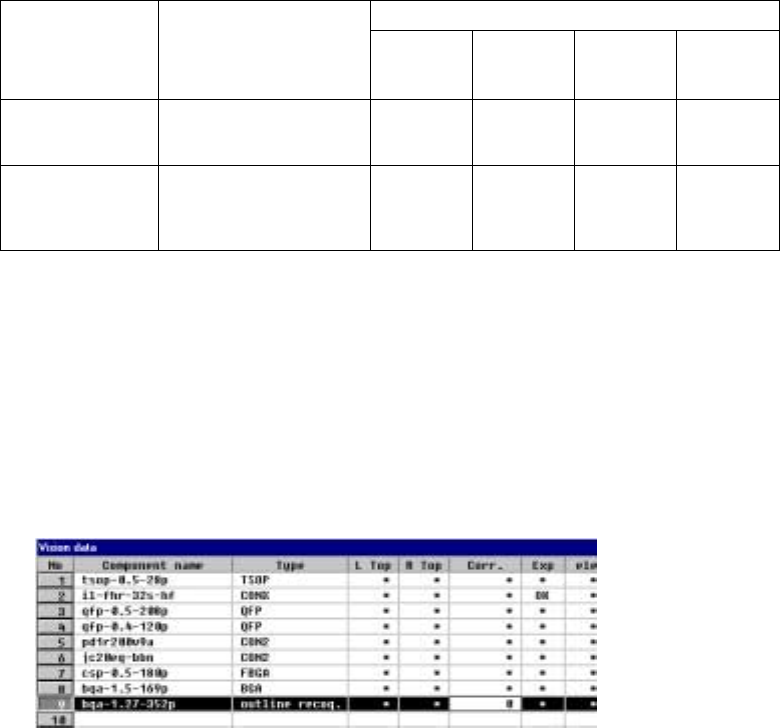
⑱ Corr.(Brightness correction)
Set the threshold to be applied when the machine recognizes an
outline-recognized component.
- “0” is set as the initial value. If the machine cannot recognize such a
component, adjust the initial value between – 127 and + 127. When a
component looks darker, set the smaller number. When you can see even
the background of a component, increase the value.