KE2040Instruction Manual Ver2.01,REV04.2003.6.25.pdf - 第412页
5 − 68 ④ Dimension For a ball/land element, the dimension is t wo. Select “ 2D”. Note: For arrang ement of only one column and one row, specif y “2D” also. ▼ Figure 5. 2.4.4.3 shows the pitch of each element group. - In …
5 − 67
Bottom View
13245
123456
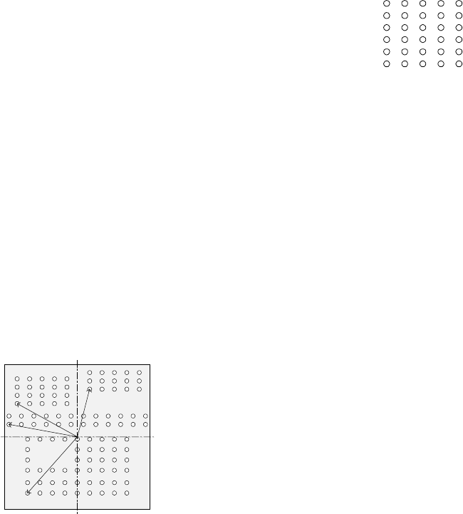
▼ To be precise, the “First element position” is
the distance (offset) from the center of a
component to the first element.
The direction (angle) of the element group is
basically 0 degrees.
Figure 5.2.4.4.14 shows the relation between
the lines (rows) and columns.
The first (ball or land) element positions at the
coordinates of the element (ball/land) at the
lower left corner.
- This layout of elements is different from that of a standard BGA
component having balls on the outer frame.
▼ Figure 5.2.4.4.15 shows the first element (ball/land) position of the
component shown in the example above.
For a ball/land element, the center of the first ball/land viewed from the
center of a component becomes the coordinates of the first (ball/land)
element.
Figure 5.2.4.4.15
③ When the first lead end is set to (- 6.0 mm, - 5.0 mm), set each value in the
“First element position” field as follows:
Offset X: - 6.0
Offset Y: - 5.0
Offset Z: 0 (not used)
Offset Theta: 0
- Normally, enter “0” to each field of the setting item “Tolerance”.
• Next, set the element group arrangement.
To set the arrangemen, the setting items “Dimension”, and “Count” and “Pitch”
of the “Column” and “Row” are provided.
Line
(row)
number
Column number
Figure 5.2.4.4.14
Bottom View
Center of a component
(Center of the component outline)
5 − 68
④ Dimension
For a ball/land element, the dimension is two. Select “2D”.
Note: For arrangement of only one column and one row, specify “2D” also.
▼ Figure 5.2.4.4.3 shows the pitch of each element group.
- In the example, the number of lead columns located in the first element
group is nine. Enter “9” to the “Count” field displayed under the setting
item “Column”.
Note: For arrangement of only one line, enter “1”.
- When the pitch is 1.5 mm, enter “1.5” to the “Pitch” of the “Column” field.
Note: For arrangement of only one line, enter “1.5” also.
- Normally, enter “0” to the “Tolerance” field.
- Since the number of lead rows located in the first element group is six,
enter “6” to the “Count” field of the “Row” setting item.
Note: For arrangement of only one row, enter “1” to the “Count” field.
- When the pitch is 1.27 mm, enter “1.27” to the “Pitch” field of the “Row”
setting item.
Note: For an arrangement of one row only, enter “1.27” to the “Pitch”
field too.
- Normally, set “0” to the “Tolerance” field.
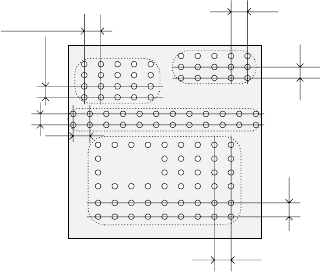
▼ The pitch of each element group is shown in Figure 5.2.4.4.16.
Figure 5.2.4.4.16
⑤ Layout inspection
This item is not used by the current version.
Bottom View
Pitch of the “Column” of the third
element group
Pitch of the “Row” of the third
element group
Pitch of the “Row” of the second
element
g
rou
p
Pitch of the “Column” of the
second element group
Pitch of the “Column” of the
fourth element group
Pitch of the “Row” of the fourth
element group
Pitch of the “Row” of the
first element
g
rou
p
Pitch of the “Column” of
the first element group
5 − 69
⑥ Missing Elements
In the example, there is missing balls (lands) on the first element group. If
there is/are a missing ball(s)/land(s), specify this setting item also in the same
manner as that of a BGA/FBGA.
Up to four blocks of missing balls/lands can be specified per element group.
To specify a block, set the first missing ball/land position of the column and
row respectively and the number of lines having missing balls/lands located
continuously in the same manner when you set those of a BGA/FBGA
component.
- If there is no ball/land on three columns from the second column and no
balls/lands on two rows from the fourth row, enter values as shown below:
“Start” of the “Column” field: 2
“Count” of the “Column” field: 3
“Start” of the “Row” field: 4
“Count” of the “Row” field: 2
Note: If there is no ball/land at five or more portions, divide the element
group further, then define those divided element groups.
♦ - Here, you have finished setting an element group.
- Next, define a recognition element of this element group.
Only one element can be defined per element group. Even though you
define two or more elements, they are handled as “invalid”.
Click the <Add> button in the “Element” setting field.
3. “Element” screen
① Type
You can specify a ball or land as an element type of ball components. This
version does not support a column.
When you specify a land as an element, you can select a circular land or
rectangular land.
For a bump, specify “Ball” as an element type from the “Type” combo box.
For an electrode that is flat entirely, specify “Land”.
- In the example, a ball is used. Select “Ball” from the “Type” combo box.
② Reference pos. (position)
The reference position of a ball/land element is the center of an element.
- Select “Center of an element” from the “Reference pos.” combo box.
③ Polarity
This item specifies the brightness of the shot image of an element.
- Normally, the light that illuminates a ball/land element brightly is used for
ball components. Select “Bright” from the “Polarity” combo box.
Note: Since a CBGA illuminates the surroundings of a ball, select “Dark”.
④ Offset
Normally, this setting item is not used. Enter “0” to each field of this item.