KE2040Instruction Manual Ver2.01,REV04.2003.6.25.pdf - 第415页
5 − 71 All of t he entered data is shown below. Figure 5.2.4. 4.17 Element Group Name First element position Layout inspectio n (Dimension) Missing Elements Element Element Offset Element size (Shape) Inspection ELG0001 …
5 − 70
⑤ Element size
Enter the size of an element.
Since the shape of a rectangular land is still a square, enter the same value to
both the “Width” and “Length” fields.
- In the example, the diameter is assumed to be 0.5 mm. Enter the following
values.
Width: 0.5
Length: 0.5
- Normally, the “Tolerance” setting item is not used. Do not change this field
setting “0”.
⑥ Ball/Land
For a land, you can select a circular land or rectangular land. Click the
corresponding check box.
- In the example, a ball element is used, so these check boxes do not appear
on the screen.
⑦ Inspection
Click the check box of the item to be inspected.
The check items “Diameter” and “Area” are the same as those for a
BGA/FBGA. Specify the corresponding check level in %. The default value
for each check level is 50 %.
Specify the check level of the “Ball exist?” check in %. also However, the
percentage indicates the internal evaluated characteristics. Normally use the
default value, “30 %”. For a land element, this item is handled as “invalid”
even though you specify this item, and the machine does not perform the
check to see if a ball exists on a component.
- Normally, the setting item “Average diameter” is not used.
- If you perform the “Diameter”, “Area” and “Ball exist?”checks with specifying
the default value respectively, the following values are used for each check:
Inspection Area: 50 % (default)
Diameter: 50 % (default)
Ball exist: 30 % (default)
Average diameter:
You have to click each check box only.
• Here, you have finished entering data on an element. When you click the
<OK> button at the lower right corner, the “Element Group” screen reappears.
You have finished defining the first element group. When you click the <OK>
button at the lower right corner, the “Extended Vision” screen reappears.
If you have another element group to be defined, click the <Add> button again
to enter data on the element group. In the example, there are four element
groups. Define four element groups.
When you finish defining all element groups, click the <OK> button at the lower
left corner to finish entering the Extended vision data.
5 − 71
All of the entered data is shown below.
Figure 5.2.4.4.17
Element
Group
Name
First
element
position
Layout
inspectio
n
(Dimension)
Missing
Elements
Element
Element
Offset
Element size (Shape) Inspection
ELG0001 X: -6.0
Y: -5.0
Z: 0
θ: 0
Tolerance:
All set to “0”.
0%
√ 2D
Count of Column: 9
Pitch: 1.5
Count of Row: 6
Pitch: 1.27
Tolerance: 0
Column
Start: 22
Count: 3
Row
Start: 4
Count: 2
Type: Ball
Reference pos.:
Center of element
Polarity: Bright
Offset: all
set to “0”.
Tolerance:
all set to “0”.
Element size
Width: 0.5
Length: 0.5
Tolerance:
all set to “0”.
(Since an element
is a ball, the
selection screen
does not appear
which allows you
to select a circular
or rectangular
shape.)
Diameter:
50
Area: 50
Ball exist?:
30
Average
diameter: 0
ELG0002 X: -8.25
Y: 1.5
Z: 0
θ: 0
Tolerance:
All set to “0”.
0%
√ 2D
Count of Column:
12
Pitch: 1.5
Count of Row: 2
Pitch: 1.0
Tolerance: 0
Type: Ball
Ref
erence pos.:
Center of element
Pol
arity: Bright
Offset: all
set to “0”.
Tolerance:
all set to “0”.
Element size
Width: 0.5
Length: 0.5
Tolerance:
all set to “0”.
(Since an element
is a ball, the
selection screen
does not appear
which allows you
to select a circular
or rectangular
shape.)
Diameter:
50
Area: 50
Ball exist?:
30
Average
diameter: 0
ELG0003 X: -7.5
Y: 4.0
Z: 0
θ: 0
Tolerance:
All set to “0”.
0%
√ 2D
Count of Column: 5
Pitch: 1.5
Count of Row: 4
Pitch: 1.0
Tolerance: 0
Type: Ball
Ref
erence pos.:
Center of element
Pol
arity: Bright
Offset: all
set to “0”.
Tolerance:
all set to “0”.
Element size
Width: 0.5
Length: 0.5
Tolerance:
all set to “0”.
(Since an element
is a ball, the
selection screen
does not appear
which allows you
to select a circular
or rectangular
shape.)
Diameter:
50
Area: 50
Ball exist?:
30
Average
diameter: 0
ELG0004 X: 1.5
Y: 5.5
Z: 0
θ: 0
Tolerance:
All set to “0”.
0%
√ 2D
Count of Column: 5
Pitch: 1.5
Count of Row: 3
Pitch: 0.8
Tolerance: 0
Type: Ball
Ref
erence pos.:
Center of element
Pol
arity: Bright
Offset: all
set to “0”.
Tolerance:
all set to “0”.
Element size
Width: 0.5
Length: 0.5
Tolerance:
all set to “0”.
(Since an element
is a ball, the
selection screen
does not appear
which allows you
to select a circular
or rectangular
shape.)
Diameter:
50
Area: 50
Ball exist?:
30
Average
diameter: 0
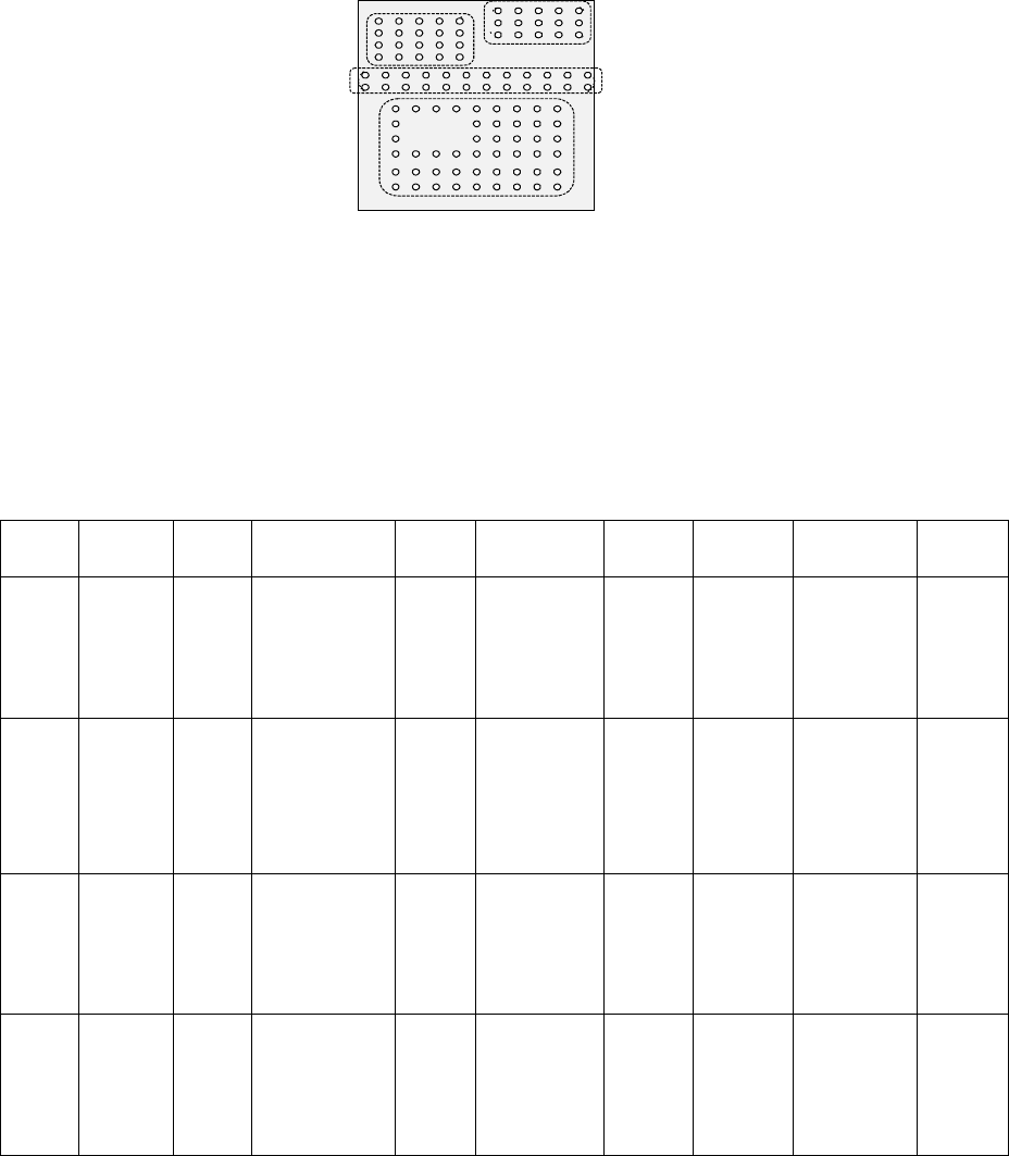
Bottom View
Third element group
(X, Y): (-7.5, 4.0) mm
Pitch of Column: 1.5 mm, Count: 5
Pitch of Row: 1.0 mm, Count: 4
Missing Elements: none
Ball diameter: 0.5 mm
Inspection: Area 50 %
Diameter 50 %
Ball exist? 30 %
Forth element
(X, Y): (1.5, 5.5) mm
Pitch of Column: 1.5 mm, Count: 5
Pitch of Row: 0.8 mm, Count: 3
Missing Elements: none
Ball diameter: 0.5 mm
Inspection: Area 50 %
Diameter 50 %
Ball exist? 30 %
Second element
(X, Y): (-8.25, 1.5) mm
Pitch of Column: 1.5 mm, Count: 12
Pitch of Row: 1.0 mm, Count: 2
Missing Elements: none
Ball diameter: 0.5 mm
Inspection: Area 50 %
Diameter 50 %
Ball exist? 30 %
First element
(X, Y): (-6.0, -5.0) mm
Pitch of Column: 1.5 mm, Count: 9
Pitch of Row: 1.27 mm, Count: 6
Missing Elements:
Start 2 Count 3
Start 4 Count 2
Ball diameter: 0.5 mm
Inspection: Area 50 %
Diameter 50 %
Ball exist? 30 %
5 − 72
5.2.4.5 Limitations of a general-purpose vision component
1. Quantity
- Up to 20 element groups can be defined per component.
- Only one extended array group can be defined per component.
- The maximum number of lead elements that can be defined per element group
is 384, and that of ball elements is 6936. These numbers include missing
leads/balls.
- One corner/side/mark element should be defined per element group
respectively.
- The maximum number of ball elements that can be defined per extended array
group is 256.
- Up to four blocks of missing elements can be defined per element group. If
you want to define five or more blocks of missing elements, divide the element
group into two or more groups.
- Up to 6936 balls can be defined per component.
- Up to four corners/sides and up to three marks can be defined per component.
- The total number of element groups that can be handled with one production
program is up to 1,024.
- The total number of extended array groups that can be handled with one
production program is up to 256.
2. Combination
- Both a lead element and a ball (or land) element cannot be defined for one
component at the same time.
- Combination of elements that are seen under the same light only can be
defined for one component.
- Both an element group and an extended array group cannot be defined for one
component at the same time.
3. Lead components
- At least one element group including two or more leads has to exist on a
component.
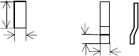
- As the lead size, the ratio of the length to width should be 1 or more. For a
gull-wing lead, the ratio of the length to the length specified in the “Lead size”
should be 1 or more.
Length Length
Width
Width
Normal lead Gull-wing lead
The length of a lead
should be longer than
the width.