KE2040Instruction Manual Ver2.01,REV04.2003.6.25.pdf - 第419页
5 − 75 5. Outl ine-recognized components - If you define an out line-recog nized component with only one type of element (corner, side or mark ) ot her than a lead and ball, you have to specify two or more corr esponding…
5 − 74
4. Ball components
- At least one ball group consisting of three or more balls of the same size
should exist on a component.
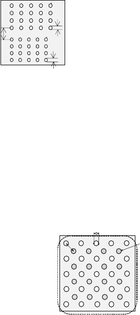
- When the similar size of ball/land groups (the diameter ratio should be less
than 1.5) are located closely, the center of one group should be far from that of
another group by 2 times of the ball/land diameter or more.
- In any case: if you define all ball groups or if you define only certain groups to
recognize them, you have to follow the requirement described above.
- For a staggered type of BGA, you can define it as two square-grid ball groups.
In this case, you can specify these two groups even though these ball groups
overlap one another. However, any ball of these groups should not overlap
with each other, and the centers of two adjacent balls of each group should be
located far from on another by 1.5 times of their diameters.
- If you specify only limited balls of one ball group, we cannot guarantee their
recognition accuracy (due to the Version 1.10 limitations).
- If the diameter check precision is the diameter ± 50 % or less, the recognizable
pitch and recognizable ball diameter are limited greatly.
- A rectangular land should be a square. (Note that the machine may
recognize an element as a lead if the ratio of the lead width to the lead length
of a rectangular land is 1 : 1 or less.)
- You cannot define a ball for two different ball groups. You cannot define balls
that overlap each other either. Note that you happen to define balls in these
ways if you set the wrong ball pitch, number of ball lines and/or ball diameter.
L
D1
D2
D1: Ball diameter of Element group 1
D2: Ball diameter of Element group 2
L: Distance between the centers of the two
adjacent balls
When D1 < 1.5D2 or D2 < 1.5D1,
L
≧
2D1 and L
≧
2D2
<BOTTOM VIEW>
D
L
D: Ball diameter
L: Distance between the
centers of two adjacent balls
L >= 15
<BOTTOM VIEW>
Element
g
roup 2
Element
g
roup 1
5 − 75
5. Outline-recognized components
- If you define an outline-recognized component with only one type of element
(corner, side or mark) other than a lead and ball, you have to specify two or
more corresponding elements. If you specify another type of element also,
you only have to specify one corresponding element (excluding a side).
- Up to four corners can be specified for this type of component. Note that you
cannot specify two or more corners whose specified angle is the same (theta
offset).
- If another corner or an element (lead, rectangular land or rectangular mark)
having a corner whose angle is the same is located near one corner element,
they should be far from one another by 4 mm or more provided that the
standard VCS is used.
(Since an intersection point outside the outer frame is regarded as a corner
due to the Version 1.10 limitations, two corners (or corner-shaped substance)
should be far from one another by 4 mm or more also.)
- Up to four sides can be specified per component. However, note that two or
more sides whose specified angle is the same (theta offset) cannot be
specified per component. A side should be located on the outer frame, and
its length should be half or longer of the dimension of the component. When
you specify a side (sides) only as an element, include two sides that are
orthogonal
to one
another.
- Up to three marks can be specified per component.
- You can specify a hole as a circle mark of the reverse polarity (dark). In this
case, it has to be displayed as a circle clearly on the screen. (Note that a
hole may not be displayed as a circle clearly on the screen when a thick
component is to be recognized with the perspective light.)
- A mark should be located far from a similar-sized mark or similar-shaped and
similar-sized element (ball or circular land) by 5 mm or more provided that the
standard VCS is used.
6. Notes when a general-purpose vision component data format is used
- Use this format for an element group (especially lead element group) whose
positioning precision is sufficient to be recognized. When you use this format
for an element group (especially lead element group) whose positioning
precision is uncertain, a recognition error may occur frequently.
ー
θ270°Corner
θ0°
Corner2
θ0°
Corner1
θ90°Corner
θ180°Corner
Although there are two corners
whose theta angle is 0 degrees, you
can specify just one corner of them.
<TOP VIEW>
ー
θ270°
Side 1
θ0°
Side 2
θ0°Corner1
θ90°Side
θ180°Side
θ270°
Side 2
Although there are two sides whose
theta angle is 0 degrees and those
whose theta angle is 270 degrees
respectively, you can specify only
either of two sides whose angle is
the same.
<TOP VIEW>
5 − 76
5.2.4.6 Operating Component Viewer
5.2.4.6.1 Opening “Component Viewer”
The “Component Viewer” dialog can be opened from the following 3 screens.
① Vision Form Screen
② Element Data Screen
③ Element Group Screen
The operating method and the contents of data to be displayed on “Component
Viewer” differ depending on the screen from which “Component Viewer” is started.
Table 5.2.4.6-1 Differences in Operating Method and Contents
of Display of “Component Viewer”
Screen from which
“Component Viewer” is
opened
For editing element data Contents of display
Opening from the Vision
Form screen
“Component Viewer” must
be closed.
All element groups are
displayed.
Opening from the Element
Data screen
“Component Viewer” does
not need to be closed.
All element groups are
displayed.
Opening from the Element
Group screen
“Component Viewer” does
not need to be closed.
Only the current element
group is displayed.