KE2040Instruction Manual Ver2.01,REV04.2003.6.25.pdf - 第43页
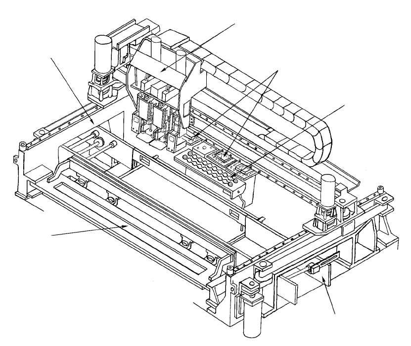
1 − 26 Figure 1.2.1. 3 ① ATC unit ④ PW B transf er unit ② Head unit ⑤ Feeder bank unit ③ X-Y unit ⑥ VCS unit ① ④ ⑤ ③ ② ⑥
1 − 25
1.2 Basic Configuration and Parts Identification
1.2.1 Entire system views
⑨
②
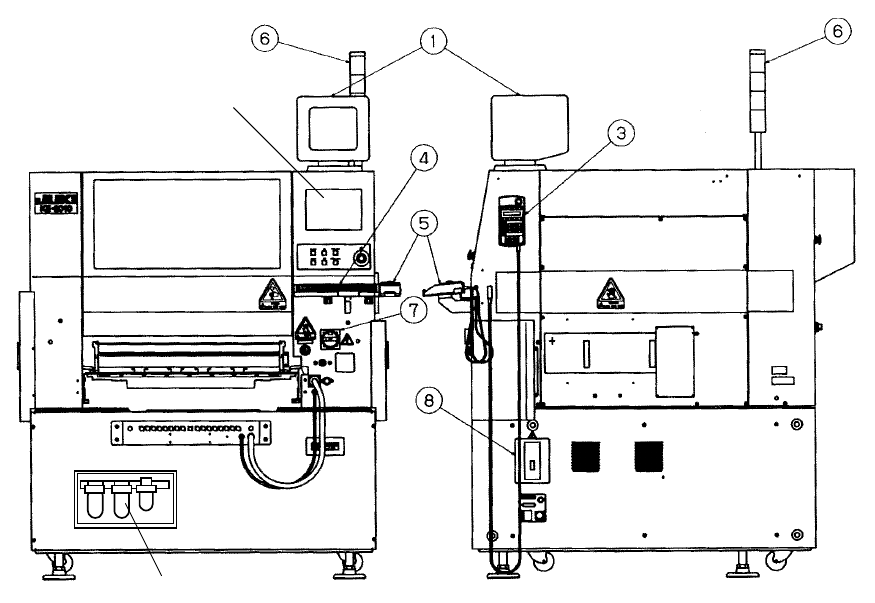
Figure 1.2.1.1 Front View Figure 1.2.1.2 Right Side View
①
Vision monitor
④
Keyboard
⑦
Main switch
②
LCD display
⑤
Track ball
⑧
No-fuse breaker
③
HOD unit
⑥
Signal tower
⑨
Filter regulator
1 − 26
Figure 1.2.1.3
①
ATC unit
④
PWB transfer unit
②
Head unit
⑤
Feeder bank unit
③
X-Y unit
⑥
VCS unit
①
④
⑤
③
②
⑥
1 − 27
1.2.2 PWB transfer unit: mechanism and parts identification
1. Pin reference
1) When a board is carried in and the IN sensor
①
detects the board, the PWB
transport motor
⑦
drives the drive shaft
⑧
to start transporting the board
with the PWB transport belt. At the same time, the stopper
⑨
is turned on.
2) When the board reaches the stopper
⑨
, the STOP 3 sensor detects it, then
the BU plate
⑫
moves up. The board is fixed with the centering pin
⑪
and
BU pin
⑭
which are attached on the BU plate
⑫
.
3) After the board is fixed, the next board is carried in the same manner, and it
waits at the Wait sensor
⑯
.
4) After production finishes, the fixed board is released, then the machine starts
ejecting it.
5) When the first board passes the C-OUT sensor
④
, the stopper is turned on
again and the next board is fixed.
2. Edge reference <Optional>
The board transfer mechanism is the same as that of the pin reference above.
When the board is fixed, edges of the boards are held by the stopper
⑨
pusher,
X
⑩
(in the X direction) pusher Y,
⑮
(in the Y direction) and BU pin
⑭
.
The transfer operation that follows is also the same as that of the pin reference
above.