KE2040Instruction Manual Ver2.01,REV04.2003.6.25.pdf - 第438页
5 − 48 (1) Setti ng items 1) Select a component type f rom t he “Component T ype” combo box at f irst: - Leaded Component - Ball Component - Out line Component 2) Define the dat a for mat. Check either one of t he corres…
5 − 47
5.2.4.2 Specifications of a general-purpose vision component
1) Quantity
- Up to 20 element groups can be defined per component.
- Only one element can be specified per element group.
2) Dimensions
Element Setting item Standard VCS Optional VCS1 Optional VCS2 Optional VCS3
Pitch 0.5 – 22.0 mm 0.4 – 15.0 mm 0.3 – 11.0 mm 0.3 – 6.5 mm
Wd (lead width) 0.22 – 10.0 mm 0.15 – 7.0 mm 0.12 – 5.0 mm 0.12 – 3.5 mm
Len (lead length) 0.4 – 10.0 mm 0.3 – 7.0 mm 0.2 – 5.0 mm 0.14 – 3.5 mm
Lead
element
Number of leads 1 to 384/element group
Pitch 1.0 – 22.0 mm 0.7 – 15.0 mm 0.5 – 11.0 mm 0.35 – 6.5 mm
Diameter 0.4 – 5.0 mm 0.28 – 3.5 mm 0.2 – 2.5 mm 0.14 – 1.5 mm
Ball/Land
element
Number of balls 3 to 6936/element group
3) Shape and size specifications of an outline-recognized component group
- The specifications of the corner/side shape are the same as those of the
outline-recognized component group (See “Limitation on components
depending on the recognition method” of “⑪ Contrast”, “5.2.3 Detailed
description of operation”).
- A filled circle and square marks can be used. A mark whose size is from 2
mm to 10 mm can be recognized with the standard VCS.
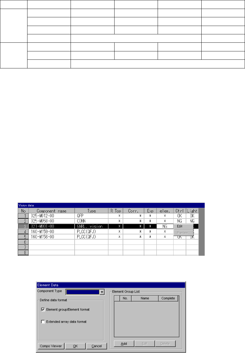
5.2.4.3 elem. (element)
This setting item is provided for components whose component type is set to “GNRL.
vision” in the “Type” cell and which cannot be recognized with normal Vision data
because their lead (ball) pitch or lead length is not the same as each other although
their component type is the same.
- When you click this setting item with the right button, the selection pop-up menu
appears on the screen as shown below.
• When you click the [Edit] command on the pop-up menu, the following screen
appears.
5 − 48
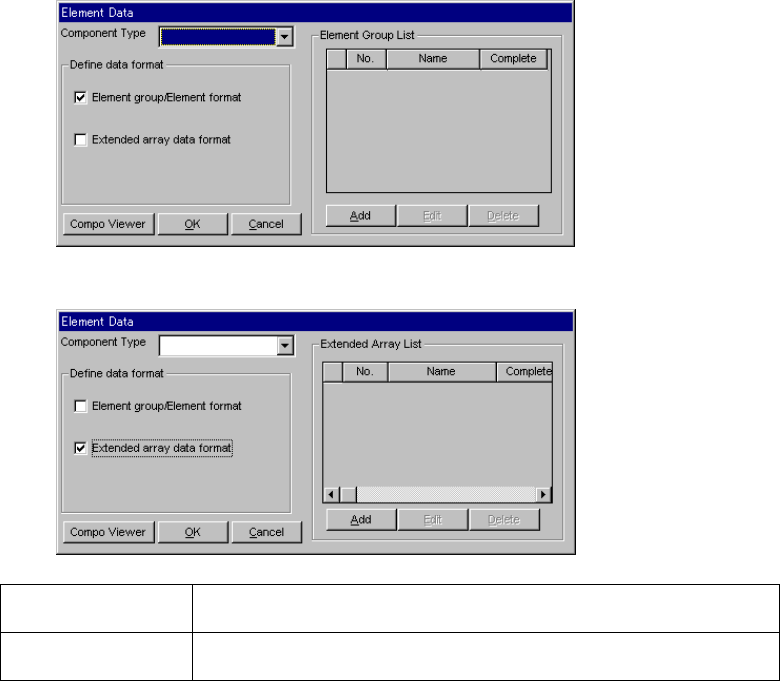
(1) Setting items
1) Select a component type from the “Component Type” combo box at first:
- Leaded Component
- Ball Component
- Outline Component
2) Define the data format.
Check either one of the corresponding check boxes for defining the data
format:
- Element group/Element format
- Extended array data format
▼ When you select “Element group/Element format”
▼ When you select “Extended array data format”
Element
group/Element format
Use this data format for a component whose elements are arranged regularly.
Extended array data
format
Use this data format for a component having an irregular ball pattern (available
only if you select “Ball Components” as the “Component Type”).
1) Editing data
- When you click the <Add> button, the detailed “Element Group” screen or
“Extended Array” screen appears which allows you to create new data.
- When you select an element group from the “Element Group List” and click
the <Edit> button, the detailed “Element Group” screen or “Extended Array”
screen appears in the same manner when you click the <Add> button to
allow you to edit the displayed data.
- When you select an element group from the “Element Group List” and click
the <Delete> button, the selected element group is deleted.
5 − 49
After data is completed, press the OK button. The editing screen reappears.
The following dialog is displayed by pressing “Component Viewer”. How to
use “Component Viewer” is described in “5.2.4.6 Component Viewer”.
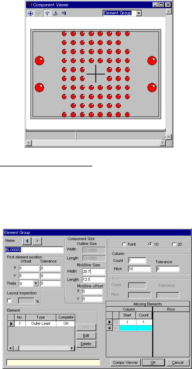
3.1 Element group/Element format
This screen allows you to group components whose lead (ball) pitch, lead
length or ball diameter is the same as each other, and create or edit data
on a group.
- Up to 20 element groups can be defined.
- When you check the “Element group/Element format” check box and
click the <Add> or <Edit> button, the following screen appears.