KE2040Instruction Manual Ver2.01,REV04.2003.6.25.pdf - 第443页
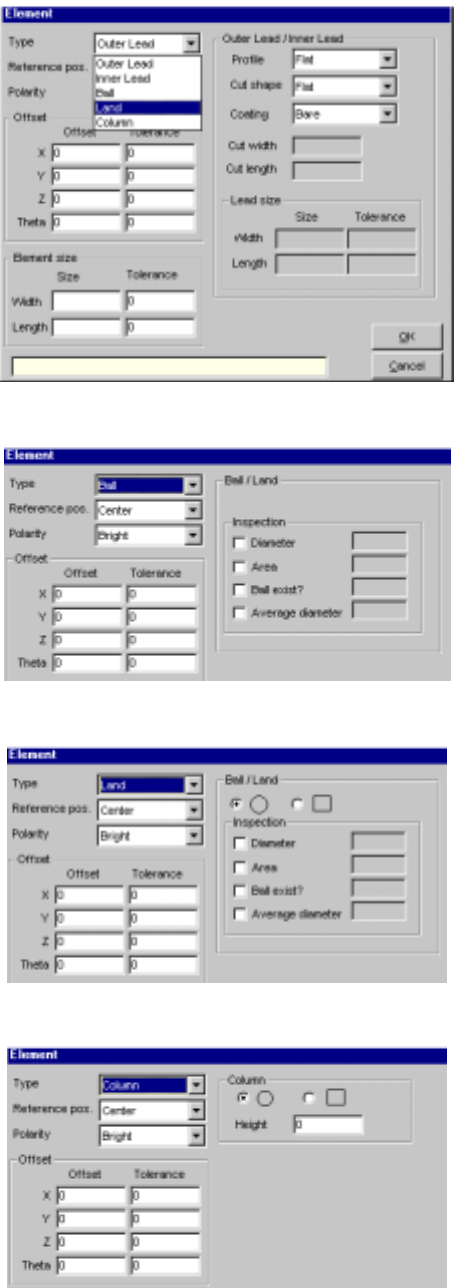
5 − 53 (1) W hen you select “ Outer Lead” or “Inner Lead” (2) W hen you select “Ball” (3) W hen you select “ Land” (4) W hen you select “ Column”
5 − 52
3-4 Detailed description of each setting item
Setting item Description
Name Enter a name (up to 32 alphanumeric characters) to be assigned to an extended
array.
You can omit this item. When omitted, “ENGxxxx” is assigned to a name, where
xxxx is a four-digit integer automatically obtained.
Location X, Y Enter the coordinates of a ball to be checked with being viewed from the center of
a component. Up to 256 balls can be defined.
Add Adds an element setting.
Edit Allows you to edit an element already set.
Element
See Section 3-5
“Element”.
Delete Deletes an element.
Layout inspection is performed by checking off the check box. Layout Inspection
Inspect Level Set the level used for checking a layout error.
OK Registers data then displays the “Extended Vision” screen where the registered
data appears on the “Extended Array List”.
Cancel Cancels your creating/editing, then displays the “Extended Vision” screen again.
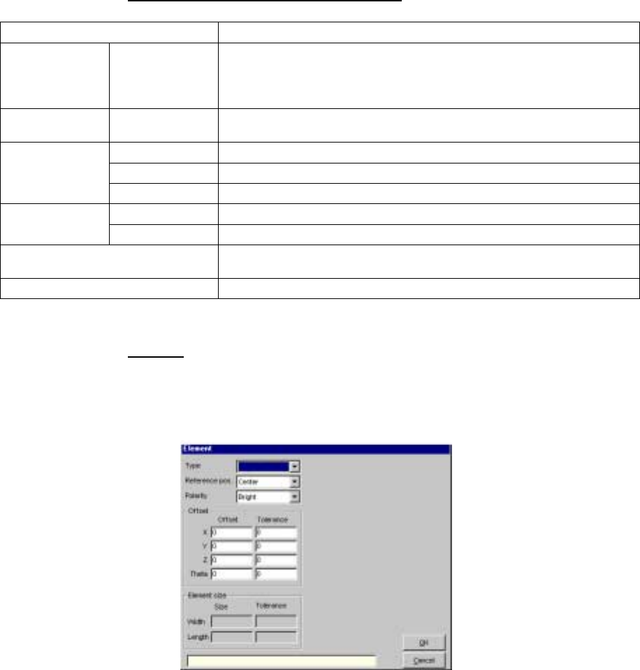
3.5 Element
When you click the <Add> or <Edit> button displayed on the “Element
Group” or “Extended Array” screen, the following screen appears.
- Set the conditions under which a lead (ball) is to be checked.
• When you select an element type from the “Type” combo box, the
following dialog box appears on the right side of the screen shown
above.
5 − 53
(1) When you select “Outer Lead” or “Inner Lead”
(2) When you select “Ball”
(3) When you select “Land”
(4) When you select “Column”
5 − 54
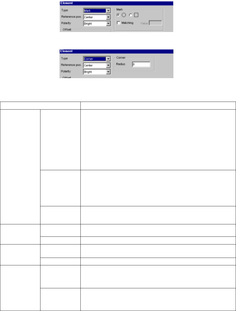
(5) When you select “Mark”
(6) When you select “Corner”
• Detailed description of each setting item
Setting item Description
Type Select an element type according to the “Dimension” setting as shown below:
1D
- Outer Lead (referred from the top view)
- Inner Lead (referred from the top view)
1D and 2D
- Ball (referred from the bottom view)
- Land (referred from the bottom view)
- Column (referred from the bottom view)
Point
- Mark (referred from the bottom view)
- Side (referred from the top view)
- Corner (referred from the top view)
Reference pos.
(position)
(A displayed
value is set, and
fixed according to
the “Type”
setting.)
Select the element reference position:
- Center: center of an element (selected when “Ball”, “Land”, “Mark” or
“Marginal area” is selected)
- Center of the bottom side: (selected when “Outer Lead”, “Inner Lead” or
“Side” is selected) (for a lead component)
- Lower left position: (selected when “Corner” is selected)
Element
Polarity Select the brightness of an element:
- Bright
- Dark
X, Y, Z and Theta Set an offset if the coordinates set in the “Element Group” screen should be
offset further. (Not used)
Offset
Tolerance Set the allowable offset range. (Not used)
Size Enter the size of an element: dimensions of a lead.
- “X” indicates the width and “Y” indicates the length.
Element size
Tolerance Set the allowable size range. (Not used)
Profile Set the lead type:
- Flat
- Gullwing
- J-bent
Outer Lead/Inner
Lead
Coating Select coating applied to a lead:
- Bare (No plating)
- Gold-plating
- Solder-plating