KE2040Instruction Manual Ver2.01,REV04.2003.6.25.pdf - 第446页
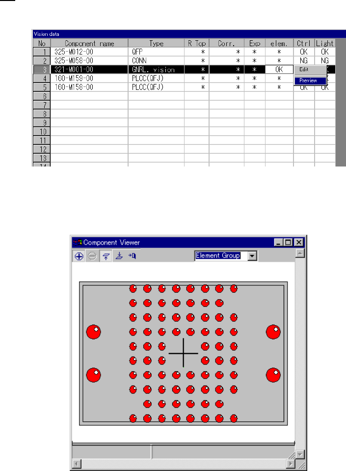
5 − 56 3.6 G eneral Vision Component Preview Function If element data is com pleted, you can select Pr eview . W hen you select Preview , the f ollowing dialog appears. How to use Component View er is described in “ 5.2.…
5 − 55
L
LL
L
W
WW
W
L
LL
L
W
WW
W
L
LL
L
W
WW
W
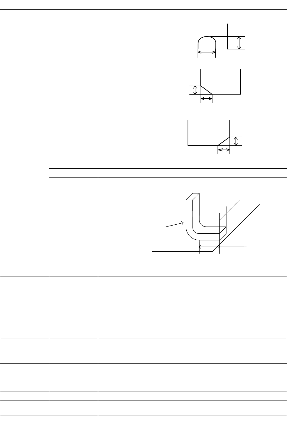
Setting item Description
Cut shape Select a cut shape of a lead:
- Flat
- U-shape cut
- Cut at the lower left corner
- Cut at the lower right corner
Cut length Enter the length of a cut portion of a lead (L).
Cut width Enter the width of a cut portion of a lead (W).
Lead size Enter the length and width of a foot portion of a lead.
Tolerance
Set the tolerance of the footprint size (width and height).
Ball Inspection –
Diameter, area,
ball/no ball,
diameter average
Check off the check box of the target item to be inspected.
Set the inspection ratio of the check item to be checked.
Mark ID
Set the shape ID according to the mark shape.
Land
Inspection –
Diameter, area,
ball/no ball,
diameter average
Check off the check box of the target item to be inspected.
Set the inspection ratio of the check item to be checked.
Mark ID
Set the shape ID according to the mark shape.
Mark
Matching
Check off the check box if it is a target for matching inspection.
Set the mark correlation matching inspection value.
Hole Mark ID
Set the shape ID according to the mark shape.
Mark ID
Set the shape ID according to the mark shape.
Column
Height
Set the column height.
Corner Corner
Set the corner R value.
OK Registers data and displays the “Element Group” or “Extended Array” screen
again.
Cancel Cancels data registering and displays the “Element Group” or “Extended Array”
screen again.
Length
Width
Lead
Board
5 − 56
3.6 General Vision Component Preview Function
If element data is completed, you can select Preview.
When you select Preview, the following dialog appears.
How to use Component Viewer is described in “5.2.4.6 Component Viewer”.
5 − 57
5.2.4.4 Procedure for creating general-purpose vision component data
5.2.4.4.1 Lead components (Element group/Element format)
This section describes the procedure for creating data on lead components
(multi-lead components).
1) Operation on the “Extended Vision” screen
- Select “Lead Component” on the “Component Type” combo box.
- Check the “Element group/Element format” check box in the “Define data
format” field.
- Click the <Add> button on the “Element Group List”.
2) Operation on the “Element Group” screen
Define an element group on this screen.
An element group is composed of components whose lead size and pitch are the
same.
See Figure 5.2.4.4.1 for an example of a multi-lead component. The procedure
for creating data on this component is to be described below.
▼
▼▼
▼ Description
In the example below, four element groups are defined. The size and pitch of
leads of the first and third element groups are the same, while the direction and
position of leads of these groups are different from each another. The size and
pitch of leads of the second and fourth element groups are the same also, but
leads of these groups are not arrange continuously, so the lead pitch is not the
same. If the distance between these leads is an integral multiple of the specified
pitch, they can be defined as one element group that has an area having no lead.
However, we recommend that you define them as separate element groups.
To define the direction and position of the element group, specify the component
posture. In Figure 5.2.4.1.1, the direction of a component shown is normal. The
posture of multi-lead components is regulated from the top view.
Figure 5.2.4.4.1
Fourth element
group
Third element
group
Second element
group
First element
group
Top View